
作成者: デニスRuest, 工学博士/IPQDF
スキルレベル: 高度なDIY (電気の経験が必要です)
電圧: 120/240V 分割相
システムサイズ: 5キロワット (キロワット)
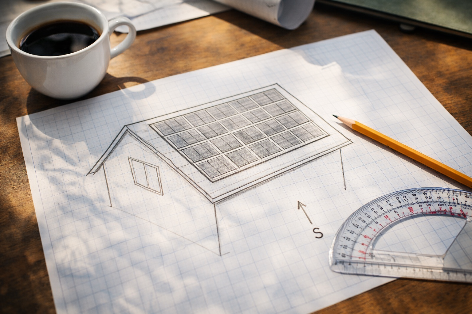
1. はじめに: 目標を理解する
5kWの太陽光発電システムは、中規模の住宅のほとんどに電力を供給できる重要な投資です。. 使い方14 パネル (よりもむしろ 13) バランスの取れた弦構成、つまり 2 つの等しい弦を作成します。 7 パネルごとに配線を簡素化, 電気的バランスを改善する, トラブルシューティングが容易になります.
部品を購入する前に, あなたが決めなければなりません: グリッドタイドまたはオフグリッド?
- グリッドタイド: ユーティリティへの接続は維持されます. 電力を売り戻すことができる (ネットメータリング) ただし、送電網の停止中は安全のためシステムがシャットダウンします。 (単独行動防止). 5kW 系統連系システムは通常、 20-25 1日あたりのkWh, 平均的な家庭の使用量を補うのに十分な量.
- オフグリッド: ユーティリティから完全に独立しています. 大量のバッテリーバンクが必要 (48V@200Ah以上). システムが動作します 24/7 グリッドに関係なく. 5kWのオフグリッドシステムで冷蔵庫を稼働可能, ライト, エレクトロニクス, 小型のエアコンや井戸ポンプもサイクルで使用可能.
免責事項: 電気を扱う作業は危険です. 最終的な接続については、資格のある電気技術者に相談してください。. この規模のシステムには、地元の管轄区域によって許可が必要です. この記事は情報提供を目的としており、資格のある専門家に代わるものではありません。.
2. なぜ 14 パネル? 偶数の利点
使い方 14 パネル (2つの文字列 7) に比べて大きなメリットをもたらします 13 パネル:
| 特徴 | 13 パネル (7+6) | 14 パネル (7+7) |
|---|---|---|
| 弦バランス | 等しくない文字列 | 完璧なバランス |
| 電圧マッチング | 異なるストリング電圧 | 同一のストリング電圧 |
| コンバイナーボックス | 別の融着が必要 | 両方の弦に同じヒューズを使用 |
| パフォーマンス | 1 つの文字列の生成量が少なくなる | 両方からの同等の生産 |
| 拡張性 | ぎこちない構成 | 後で簡単にペアを追加できます |
| 総電力 | ~5.0kW (385Wパネル搭載) | ~5.4kW (385Wパネル搭載) |
とともに 14 × 385W パネル, わかります5,390で- ほとんどの 5kW インバーターに過負荷をかけることなく、曇りの日に役立つ 5kW を超える優れたバッファー (通常は最大 6,000W DC 入力を受け入れます).
3. ツール & 材料チェックリスト
必要なツール:
- ドリル & インパクトドライバー 六角ビット付
- ソケットセット & レンチ (メートル法と標準)
- ワイヤーストリッパー/カッター (10 AWGから 2/0 AWG対応)
- 最大 600V の DC 電圧機能を備えたデジタル マルチメーター
- PV (太陽) 安全手袋 (絶縁された)
- トルクレンチ (インチポンドとフィートポンド)
- スタッドファインダー (電子)
- チョークライン
- 電線管ベンダー (1/2″ そして3/4″)
- フィッシュテープ
- ケーブルラグ圧着工具 (バッテリーケーブルには油圧式を推奨)
5kWシステムの材料 (14 パネル):
太陽電池アレイ:
- ソーラーパネル: 14× 360W~400Wパネル (合計5.0~5.6kW). 屋根スペースを最小限に抑えるために高効率の単結晶パネルを選択してください.
- ラッキングシステム: アルミレール, Lフィート, 中間クランプ, エンドクランプ, 点滅する (アイアンリッジ, ユニラック, またはスナップナラック). お住まいの地域の風雪荷重に対する定格を確認してください.
- 接地: アース端子, WEEBワッシャー, または銅線.
直流電気:
- コンバイナーボックス: 2弦機能を備えた耐候性エンクロージャ.
- ストリングヒューズ: 15各弦のヒューズまたはブレーカー (2 必須, 同一の評価).
- PVワイヤー: 10 AWGまたは 8 パネル相互接続用の AWG, 6 ホームラン用AWG.
- DC切断: 30A または 60A 屋外定格安全スイッチ.
インバータ:
- 系統連携オプション: 5kWストリングインバーター (SMA, ソーラーエッジ, フロニウス) または 5kW のマイクロインバーター (エンフェーズ IQ8+). 最大 DC 入力が最大 5.4kW に対応することを確認します。.
- オフグリッドオプション: 5kW分相充電コントローラ内蔵オールインワンユニット (グロワット SPF 5000 これは, MPP ソーラー LVX6048, ビクトロン マルチプラス II). 48V DC 入力を受け入れる必要があります.
交流電気:
- ACブレーカー盤: メインパネルまたはサブパネル.
- 二極ブレーカー: 30A ソーラーバックフィード用.
- THHNワイヤー: 10 AWG銅 (色分けされた: 黒, 赤, 白, 緑).
- AC切断: 屋外定格安全スイッチ (コードで必要な場合).
オフグリッドのみ:
- バッテリーバンク: 48V リン酸鉄リチウム (LiFePO4) バッテリー. 最小100Ah (5キロワット時), 推奨200Ah (10キロワット時) 夜間の荷物の場合. 例: EG4 LL, トロフィーバッテリー, パイロンテック.
- バッテリーケーブル: 2/0 AWGまたは 4/0 ラグ付き AWG 溶接ケーブル.
- クラス T ヒューズ: 250Aまたは300A ホルダー付.
- バスバー: バッテリー接続用の頑丈な銅バスバー.
- バッテリーラック: サーバーラックまたはシェルフシステム.
消耗品:
- ワイヤーナット / ワゴコネクタ
- ケーブルタイ (屋外でも使える耐紫外線性)
- 導管 (スケジュール 40 PVC または EMT)
- 浸透シーラント (屋根コーキング)
- 絶縁テープ
- ラベルメーカー / 耐紫外線ラベル
4. システム設計 & レイアウト (書類作成フェーズ)
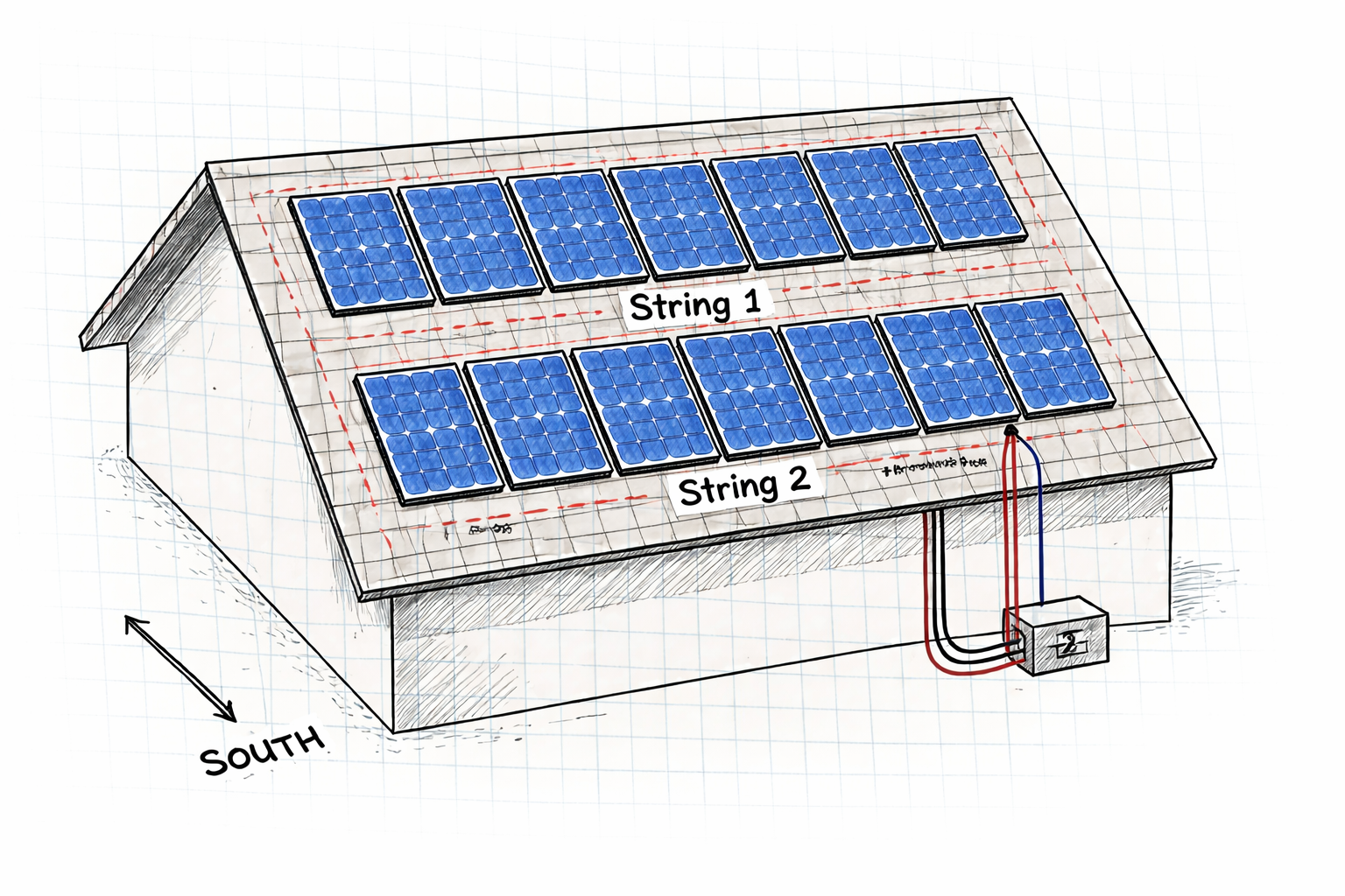
一枚のパネルを持ち上げる前に, 紙の上でデザインを完成させる必要があります. これは許可のために必要であり、コンポーネントが安全に連携することを保証します。.
手順 4.1: 屋根の評価
- 向き: 北半球では南向きが最適. 南東か南西は負ける 10-15% 生産.
- ピッチ: ほとんどの屋根は機能します, しかし急ピッチ (45°を超える) 特別な安全装置が必要です.
- 状態: 屋根に少なくとも 10 残りの人生の年数. 太陽光発電設置後の屋根の葺き替えは費用がかかる.
- 障害物: 煙突からの距離を測定する, 通気口, そして天窓. 必要です 18-36 火の侵入を防ぐためにアレイの周りに数インチの隙間を設ける (ローカルコードを確認する).
- レイアウト: とともに 14 パネル, 2列に並べることができます 7 (横向き) または7行 2 (縦向き). 2列の 7 最も一般的です.
手順 4.2: 文字列サイズの計算 (完璧なバランス)
とともに 14 パネル, 2つの同一の文字列を作成します 7 パネルごと.
- パネル電圧: 最新の 400W パネルのほとんどには Voc があります。 (開路電圧) 40~45V程度.
- 文字列A: 7 パネル x 45V = 315V (オペレーティング) / 365で (最高低温温度)
- 文字列B: 7 パネル x 45V = 315V (オペレーティング) / 365で (最高低温温度)
- 総電力: 両方の文字列が結合ボックスで並列に結合されます。, 同一の電圧と平衡電流を生成する.
致命的: 文字列サイズ計算ツールを使用する (インバータメーカーのウェブサイトで入手可能) お住まいの地域の記録的な低温により、. 正しく計算されていない場合、寒さにより電圧が上昇し、インバーターが破損する可能性があります. 7パネルストリング付き, 一般的な最大 600V インバータ入力よりも低い安全マージンが十分にあります。.
手順 4.3: 生産見積り
5.4kWシステム (14 ×385W) のあるエリアで 5 太陽のピーク時間が生成されます:
- 毎日: 5.4kW×5時間× 0.8 (システム損失) =21.6 kWh/日
- 毎月: 21.6 キロワット時× 30 =648 kWh/月
- 毎年: 季節により異なります, 一般的に 7,000-9,000 kWh/年
これはカバーします 60-100% 効率に応じた平均的な家庭の使用量.
手順 4.4: 許可する
地元の建築部門を訪ねて、:
- 屋根の寸法を示す敷地図
- パネル配置図 (14 パネルが明確に示されている)
- 電気単線図
- 設備仕様書
- 構造計算 (必要に応じて)
機器の購入または設置を開始する前に承認を待ってください.
5. ラックを取り付ける (取り付け金具)
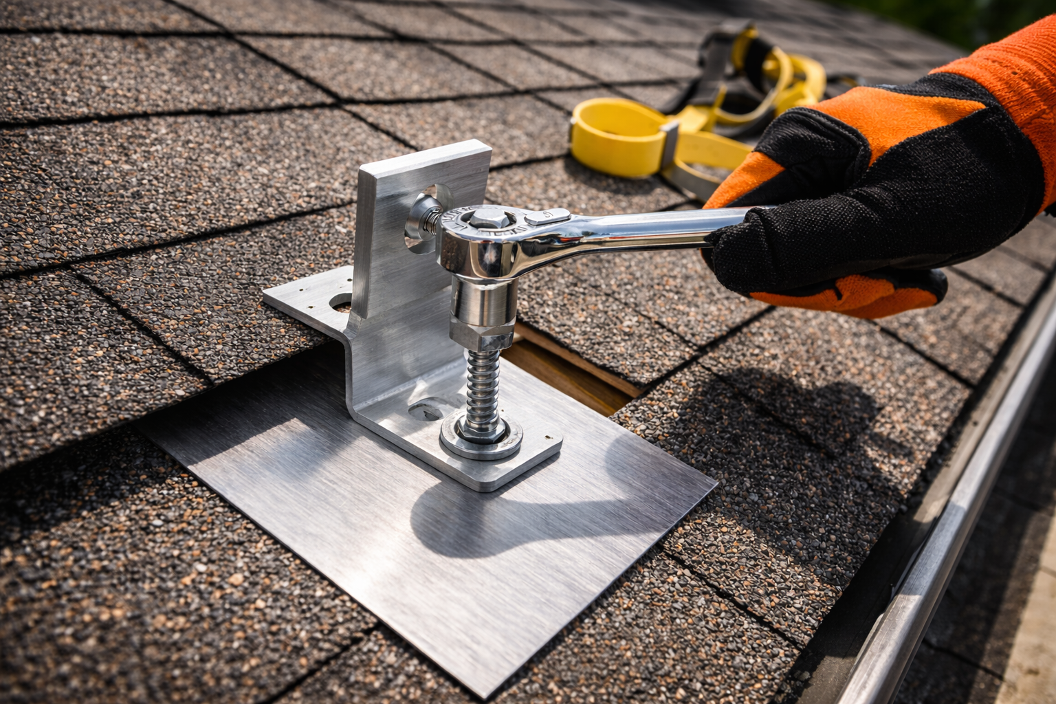
ラックシステムは太陽電池アレイの基礎です. 5kWシステム 14 パネルの重量はおよそ 650-850 ポンドであり、風による揚力に耐えなければなりません.
手順 5.1: 垂木を見つける
- 電子スタッドファインダーを使用して垂木を見つけます. 屋根部分にチョークの線で印を付けます.
- 標準垂木の間隔は24です″ 中心に. 間隔が広い場合, 構造補強が必要です.
- すべての垂木の位置を明確にマークします。これはすべての取り付けポイントで必要になります.
- のために 14 2列のパネル, 垂木とレールの各交差点に取り付けポイントが必要です.
手順 5.2: フラッシングをインストールする
- マウントを取り付ける場所の屋根板を慎重に持ち上げます. 屋根板のひび割れを防ぐためにフラットバーを使用する.
- アルミニウムの水切りを屋根板の下に完全にスライドさせます, トップエッジが上のコースの下にある.
- 水切りにはシーラントが組み込まれているか、その下に屋根用コーキングを塗布する必要があります.
手順 5.3: L字足を取り付ける
- 水切りを通して垂木の中心に下穴をドリルで開けます。. ドリルビットにストップを付けて、ドリルが深すぎるのを防ぎます.
- ラグボルトを差し込みます (通常 3/8″ ×4″ ステンレス鋼) ワッシャー内蔵.
- しっかりと締めますが、締めすぎないでください. 目標は、フラッシングを変形させずに圧縮することです。.
- 追加の屋根用コーキング剤でボルトの頭をシールします。.
手順 5.4: レールの取り付け
- T ボルトとキャップを使用して、アルミニウム製クロス レールを L フィートに取り付けます。.
- のために 14 2列のパネル 7, アレイの幅全体に渡る 2 本の水平レールが必要です.
- レールが左右および前後で完全に水平であることを確認します. 4フィートの水準器を使用する.
- 使用可能なレールの長さより長い場合は、内部スプライスを使用してレール セクションを結合します。. スプライスがしっかりと真っ直ぐであることを確認してください.
安全上のヒント: ルーフアンカー付きハーネスを常に着用してください. 屋根から転落すると致命傷になる可能性がある.
6. ソーラーパネルを取り付ける
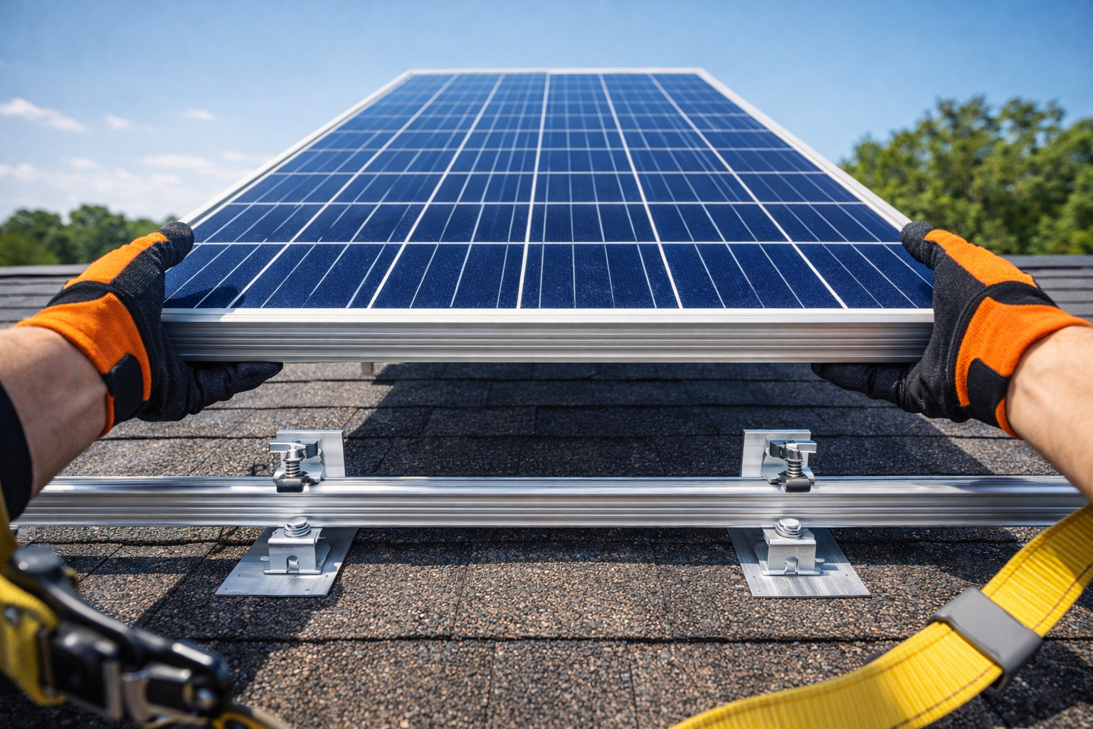
手順 6.1: パネルを安全にステージする
- パネルリフターを使用してパネルを屋根に持ち上げます, ルーフフック, または慎重に手渡します.
- とともに 14 パネル, 系統的に作業する - 一度に 1 列ずつパネルをステージングする.
- 配線の準備中にガラスを保護するために、パネルを下向きにしてフォームパッドの上に置きます.
手順 6.2: プリワイヤー (オプションですが推奨されます)
- アクセス可能な場合, 取り付ける前に、MC4 延長ケーブルをパネル ジャンクション ボックスに取り付けます。.
- これは、パネルが取り付けられている場合よりも、地面に置いたり、パネルを裏返した状態で行う方が簡単です。.
- のために 14 パネル, あなたは持っています 14 ポジティブで 14 ネガティブなリードを整理する.
手順 6.3: パネルを配置する
- 配列の一隅から開始します. 最初のパネルをレール上に置きます.
- 列を越えて作業する, 次に2行目を開始します.
- パネルはレール上に設置し、フレームはクランプ上に置く必要があります。.
手順 6.4: クランプで固定
- 中間クランプ: パネル間に使用. 隣接する 2 つのパネルのフレームをレールにクランプします。. およそ必要になります 22 中間クランプ.
- エンドクランプ: 各レールの端で最後のパネルを固定するために使用されます。. 必要になります 4 レールごとのエンドクランプ (8 合計).
- すべてのクランプをメーカーの仕様に従って締め付けます (一般的に 15-20 フィートポンド). トルクが不足するとパネルが吹き飛ばされる危険があります; 過剰なトルクはフレームに亀裂を与える可能性があります.
手順 6.5: アレイを接地する
- WEEBを使用する (ワッシャー電気機器ボンド) レールとパネルフレームの陽極酸化皮膜を突き刺すクリップ.
- あるいは, 記載されている接地ラグを使用して、各レールにボンディングされた連続裸銅接地線を配線します。.
- アレイアースを家庭の接地電極システムに接続します.
7. 電気配線 (DC側)
[画像: カチッと音がする MC4 コネクタの拡大図, 次に図を示します 2 同一の文字列 7 コンバイナーボックス内で結合するパネル]
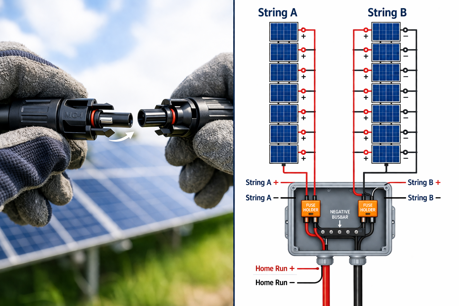
とともに 14 パネル, 完全に一致する 2 つの文字列を作成します 7 パネルごと.
手順 7.1: 文字列を設定する
- 文字列A (7 パネル): プラスを接続する (+) パネルの 1 ネガティブに (-) パネルの 2, などなど、すべてを通して 7 パネル. 最後には無料のポジティブが 1 つと無料のネガティブが 1 つあります.
- 文字列B (7 パネル): 残りについてもプロセスを繰り返します 7 パネル, 同じパターンに従っている.
手順 7.2: 電圧チェック
- インバータに接続する前に, 晴れた日にマルチメーターで各ストリングの電圧を測定します.
- 文字列 A は約 280 ~ 320V DC を読み取る必要があります (パネルの仕様と太陽光によって異なります).
- 文字列 B を読み取る必要があります同一電圧 文字列Aへ (1-2V以内).
- これらの値を記録として記録してください. 電圧が一致しているため、配線が適切であることが確認されます.
手順 7.3: コンバイナーボックスまでの配線
- 各弦からコンバイナーボックスの位置までプラスとマイナスのワイヤを配線します。 (通常はアレイの端付近または下の壁にあります).
- 屋外暴露および太陽光に耐えられる定格の PV ワイヤを使用する.
- 各ワイヤペアに明確にラベルを付けます: “文字列A +”, “文字列A -“, “文字列 B +”, “文字列 B -“.
手順 7.4: コンバイナーボックスの取り付け
- 耐候性コンバイナー ボックスをアレイ近くの壁または屋根の端に取り付けます。.
- 箱の中, 各文字列の正の値を15ヒューズまたはブレーカー (両方の文字列が同一である).
- 各ストリングのマイナスを共通のマイナスバスバーに接続します.
- 結合された出力は単一のプラスとマイナスのワイヤに接続されます。 (ザ “ホームラン”).
手順 7.5: ホームランを実行して DC 切断する
- コンバイナーボックスから, 走る6 AWG PV電線 (ポジティブとネガティブ) インバーター近くの屋外に取り付けられた DC 切断スイッチまで.
- ワイヤーが露出している場合は保護のためにコンジットを使用してください.
- このワイヤーにラベルを付けます “PVアレイ出力5.4kW” 両端に.
8. インバーターの取り付け & ACパネル
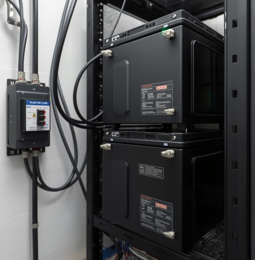
手順 8.1: 場所の選択
- 屋内 (ガレージ/地下室) インバータの長寿命化に最適です.
- 屋外ではNEMA 4X定格インバーターが必要です.
- AC 配線の配線を最小限に抑えるために、場所は主電気パネルに近い必要があります.
- オフグリッド向け, 場所はバッテリーバンクに近い必要があります (バッテリーケーブルは短くなければなりません).
手順 8.2: バックボードの取り付け
- 4をマウントする′ ×4′ 3/4枚のシート″ 壁に合板. 法令で義務付けられている場合は、難燃性塗料で塗装してください.
- これにより、しっかりとした取り付け面が提供され、機器が整理されます。.
手順 8.3: マウントインバーター
- インバータ重量: 5kW単位の重さ 50-100 ポンド. スタッドにラグボルトを使用する.
- メーカー指定のクリアランスを維持する (一般的に 6-12 すべての面でインチ) 空気の流れのために.
- インバーターが水平であることを確認してください.
手順 8.4: ACパネルを取り付ける
- 重要な負荷にサブパネルを使用する場合 (オフグリッド), インバーターの隣に取り付けます.
- メインパネルをバックフィードする場合 (グリッドタイド), メイン パネルに開いている二極ブレーカー スロットがあることを確認します。.
手順 8.5: インストールの切断
- DC ディスコネクトを取り付けます (結合箱とインバーターの間) インバーターの見えるところに.
- AC ディスコネクトを取り付けます (インバータとメインパネル間) ローカルコードで必要な場合.
9. バッテリーバンクの配線 (オフグリッドのみ)
48V で 5kW インバータの消費電力104 アンペア 全負荷時. これには、本格的なケーブル配線と安全保護が必要です.
手順 9.1: バッテリー構成の選択
- 48Vシステム: ほとんどの 5kW オフグリッド インバーターには 48V バッテリー バンクが必要です.
- 容量: 5kWの負荷を一晩稼働させる場合 (言う 10 部分負荷での時間), 少なくとも10kWhのストレージが必要です.
- 一般的なセットアップ 14 パネル: 5.4kWの太陽光発電を搭載, かなりのバッテリーバンクを充電できます. 推奨: 48@200Ahで (10キロワット時) 最小, 48V@300Ah (15キロワット時) 理想的.
- 構成オプション:
- 4x 12V 200Ah バッテリーを直列に接続 = 48V @ 200Ah (10キロワット時)
- 8x 12V 200Ah 直並列 = 48V @ 400Ah (20キロワット時)
- 3x 48V サーバーラックバッテリー並列 = 48V @ 300Ah (15キロワット時)
手順 9.2: 位置バッテリー
- バッテリーをラックまたは棚に置きます. コンクリート床の上には直接置かないでください (寒さは彼らにダメージを与える可能性があります).
- 適切な換気を確保してください。バッテリーからガスが発生する可能性があります。 (故障状態のリチウムであっても) そして熱を発生させます.
手順 9.3: ワイヤーバッテリー
- 使用2/0 AWG または4/0 AWG すべてのバッテリー相互接続用の溶接ケーブル.
- 油圧クリンパを使用して頑丈なラグをケーブルに圧着します.
- 直列接続の場合: バッテリーのプラスを接続します 1 バッテリーのマイナス側に 2, 等.
- 並列ストリングの場合: すべてのプラスをバスバーに接続します, すべてのマイナスをバスバーにまとめて接続.
手順 9.4: クラス T ヒューズの取り付け
- 致命的: Class-T ヒューズを内部に取り付けます 12 バッテリーのプラス端子のインチ.
- ヒューズのサイジング: インバータ最大連続電流 x 1.25 = ヒューズのサイズ. 104A用× 1.25 = 最小 130A. ほとんどの 5kW インバータは、サージ負荷に対応するために 200A ~ 250A ヒューズを使用しています。.
- クラス T ヒューズは短絡を防止します。バッテリーは障害時に数千アンペアを供給できます。, 火災や爆発の原因となる.
手順 9.5: インバータに接続する
- ヒューズからインバーターバッテリーのプラス端子までプラスケーブルを配線します。.
- マイナスケーブルをバッテリーのマイナス母線からインバーターのバッテリーのマイナス端子まで直接配線します。.
- すべての接続をメーカーの仕様に従ってトルクで締めてください.
手順 9.6: バッテリーモニターをインストールする (オプショナル)
- シャントベースのバッテリーモニターを設置する (Victron BMV-712 または類似品) 充電状態を正確に追跡するため.
- どれだけの容量が残っているかを知るために、オフグリッド生活には不可欠です。.
10. 交流配線 (グリッドタイド & オフグリッド)
[画像: 主電気パネルの 30A 二極ブレーカーに配線する電気技師, ラベルが貼られた “太陽”]
手順 10.1: 数学を理解する
5,400 ワット数 240 ボルト =22.5 アンペア 継続的な (5.4kWフル出力時).
米国電気工事規定では、回路のサイズを次のようにする必要があります。 125% 連続負荷の:
- 22.5あ× 1.25 =28.1A
- 故に, が必要です30二極ブレーカー (28.1Aを超える次の標準サイズ).
手順 10.2: ワイヤーゲージの選択
- 30Aブレーカーの場合, 使用10 AWG銅線 (最小).
- インバータからメインパネルまでの距離が長さを超える場合 100 足, にアップグレードする8 AWG 電圧降下を防ぐために.
- 色分けされたTHHNワイヤを使用する: 黒 (L1), 赤 (L2), 白 (中性), 緑 (グラウンド).
手順 10.3: オフグリッド接続
- L1 を実行, L2, 中性, インバーター出力から専用のアースへの接地 “クリティカルロード” サブパネル.
- サブパネル内, バックアップしたい回路に標準の 15A および 20A ブレーカーを設置します (冷蔵庫, ライト, インターネット, 等).
- それらの回路をメインパネルからサブパネルに転送します.
手順 10.4: 系統連系接続 (バックフィード)
- L1 を実行, L2, 中性, インバータ出力からメインサービスパネルまでの接地.
- 30A 2 極ブレーカーを、メイン ブレーカーとは反対側のパネルの空きスロットに取り付けます。 (これは 120% ルール).
- L1をブレーカーの一方の端子に接続します, L2から他の端末へ. 中性線を中性線バスバーに接続します, 接地バスバー.
- ブレーカーにラベルを付ける “ソーラー 5.4kW” 明らかに、将来の電気技師はそれがバックフィードバックであることを知っています.
手順 10.5: ザ 120% ルール (グリッドタイドにとって重要)
- メインパネルのバスバーには定格があります (通常100A, 125A, または200A).
- 主幹ブレーカーと太陽光逆給電ブレーカーの合計が以下を超えることはできません。 120% バスバー定格の.
- 例: 125バスバー× 1.2 = 最大 150A. 100メイン + 30ソーラー = 130A, どちらが受け入れられますか.
- パネルがこれに対応できない場合, が必要です “供給側タップ” (主幹ブレーカーの前に接続), 電気技師が必要です.
11. 最終接続 & 電源投入シーケンス
[画像: 電源を入れる前にマルチメータを使用して DC 切断部の電圧をチェックする人]
手順 11.1: 電源前のチェック
- 目視検査: すべての配線接続を確認してください. 緩んだストランドを探す, 傷のある絶縁体, または間違ったルーティング.
- 極性チェック: 正が正になることを確認する, どこでもネガティブからネガティブへ. チャージコントローラーやインバーターの極性を逆にすると即座に壊れます。.
- トルクチェック: すべての端子ネジが仕様のトルクで締め付けられていることを確認してください. 接続が緩んでいるとアーク放電や火災が発生する.
- 電圧チェック (DC): DC切断時の電圧を測定. 両方のストリングが同じ電圧を示すはずです (2V以内).
- 電圧チェック (交流): メインパネルが通電されていて、電圧が 120/240V ±5% であることを確認します。.
手順 11.2: ターンオンシーケンス (グリッドタイド)
- メインパネルからインバータへのACブレーカーをオンにします (グリッド電力).
- インバータディスプレイに電源が投入され、グリッドパラメータが表示されるまで待ちます.
- 太陽電池アレイからの DC 切断をオンにします.
- インバーターは太陽光発電を検出する必要があります, グリッドと同期する (かかります 2-5 分), そしてエクスポートを開始します.
- ディスプレイの表示を確認する “生産する” または “グリッドタイド” 正のワット数のモード. とともに 14 パネル, 太陽の正午近くに 4.5 ~ 5.4kW が表示されるはずです.
手順 11.3: ターンオンシーケンス (オフグリッド)
- すべてのAC負荷がオフになっていることを確認してください.
- DCバッテリーブレーカーをオンにするか、最初に切断します.
- インバーター画面が点灯するはずです. バッテリー電圧が正しく読み取られていることを確認します.
- ソーラー DC 切断をオンにする.
- 充電コントローラーが起動し、バッテリーの充電が開始されます。 (バルクモード). 電圧が上がるはずです.
- インバータのAC出力ブレーカーをONにする.
- 小さな負荷をオンにしてテストする (光のように). インバーターが電力を供給する必要があります.
- 徐々に大きな負荷を追加してシステムの応答をテストします.
手順 11.4: 初期動作を観察する
- システムを稼働させます 30 分. 注意してください:
- 異音 (ブザー音, アーク放電)
- コンポーネントの過熱
- ディスプレイ上のエラーコード
- インバーターファンが正常に動作する
- バランスの取れた弦を使用, どちらも同等に寄与する必要があります。利用可能な場合は、文字列ごとのデータのインバーター表示を確認してください。.
12. 監視 & パフォーマンステスト
[画像: 5.4kWの発電量を備えた太陽光監視アプリを示すスマートフォンのスクリーンショット 26.5 kWh の毎日の合計]
手順 12.1: 接続監視
- 最新のパワーコンディショナーのほとんどは Wi-Fi またはイーサネット接続を備えています.
- メーカーのアプリをダウンロードしてアカウントを作成する.
- インバータのシリアル番号を使用してインバータを登録します.
- ホームネットワークに接続してデータ送信を確認する.
手順 12.2: 実稼働の検証
- 太陽の正午近くの晴れた日, 5.4kW システムは、4.6キロワット – 5.2キロワット に応じて:
- パネル温度 (ホットパネルの生産量が減少)
- 太陽に対する角度
- 大気の状態
- 生産量が大幅に減少した場合, シェーディングの問題や配線の問題を確認してください.
- 2 つの文字列を比較します。ほぼ同一の出力が表示されるはずです。.
手順 12.3: 毎日/年間の期待
- 毎日: 22-32 kWh(季節による)
- 毎月: 660-960 キロワット時
- 年間: 8,000-11,000 キロワット時 (場所によって異なります)
手順 12.4: オフグリッド特有のモニタリング
- バッテリーの充電状態を毎日追跡する.
- バッテリーがフル充電に達する時間を記録します (配列のサイズ設定が適切であることを示します).
- バッテリーが充電不足に達する時間を記録します (さらに容量が必要かどうかを示します).
- 必要に応じて、一晩中ストレッチするために使用習慣を調整してください.
13. ラベリング & ドキュメンテーション
[画像: すべてのブレーカーとワイヤーに専門的に印刷されたラベルが付いているきれいな電気パネル]
安全のためにコードには特定のラベルが必要です:
必要なラベル:
- DC切断: “太陽光発電システムの切断 – 5.4直流kW”
- AC切断: “太陽光発電ACの切断 – 5.4キロワット”
- バックフィードブレーカー: “ソーラー 5.4kW” (ブレーカー自体に)
- メインパネル: 警告ラベルの記載 “この機器は複数の供給元から供給されています – ソーラー 5.4kW” (バックフィーディングの場合)
- インバータ: 評価が見えるメーカーラベル
- コンバイナーボックス: “文字列A (7 パネル)” と “文字列B (7 パネル)” 各ヒューズに
- すべての指揮者: 電圧と電源による各終端点の識別
保管すべき文書:
- 許可承認書類
- 機器マニュアル
- 実際のワイヤ長が記載された単線図
- 保証情報
- ログイン認証情報の監視
- 緊急停止手順 (メインパネル近くのポスト)
- どのパネルがどの文字列に属するかを示すパネル レイアウト図
14. 避けるべきよくある間違い
間違い #1: アンダーサイジングワイヤー
- 5.4kW システムは大電流を消費します. 使い方 14 バッテリー接続または長時間の DC 動作のための AWG ワイヤは、電圧降下や火災の危険を引き起こします.
- ソリューション: 常に電圧降下計算ツールを使用し、NEC の電流容量表に従ってください。. とともに 14 パネル, ホームラン電流が高くなります。 6 AWG最小値.
間違い #2: 電圧に対する温度の影響の無視
- 低温によりパネル電圧が上昇する. 25°C で 40V 定格のパネルは、-10°C で 48V に達する可能性があります.
- ソリューション: お住まいの地域の記録的な最低気温を使用してストリング電圧を計算します. 7パネルストリング付き, 十分な安全マージンを持っています.
間違い #3: 文字列内でのパネル タイプの混合
- 直列のパネルは同じアンペア数でなければなりません. 並列のパネルは同じ電圧でなければなりません.
- ソリューション: 14 パネル アレイ全体に対して同一のパネルを購入する. 古いものと新しいものを混ぜないでください.
間違い #4: バッテリーヒューズのスキップ (オフグリッド)
- バッテリーは短絡時に数千アンペアを供給できます. ヒューズなし, ワイヤーが溶けて火災の原因になります.
- ソリューション: 必ずクラス T ヒューズを取り付けてください。 12 バッテリーのプラス端子のインチ.
間違い #5: 接続部にトルクを与えない
- “手で締める” 電気接続には受け入れられません. ゆるい接続アーク, オーバーヒート, そして失敗する.
- ソリューション: すべてのラグと端子にトルク レンチを使用します. トルク値を記録する.
間違い #6: 不適切な接地
- 太陽電池アレイは静電気を蓄積する可能性があり、雷に弱い.
- ソリューション: すべての金属パーツを接着します (レール, パネルフレーム) 家庭の接地電極システムに接続します.
間違い #7: を忘れて 120% ルール (グリッドタイド)
- メインパネルのバスバーに過負荷がかかると火災の危険があります.
- ソリューション: バスバー定格の計算, 主幹ブレーカーのサイズ, 設置前のソーラーブレーカーのサイズ.
間違い #8: アンバランスな弦楽器
- とともに 14 パネル, あなたには完璧なバランスを保つチャンスがあります. 不均一な弦を作らない.
- ソリューション: 両方の文字列を 7 それぞれのパネルで同じ電圧と電流を供給.
15. いつ専門家に電話するべきか
このガイドは DIY 愛好家向けです, 特定の作業には資格のある電気技師が必要です:
- メインパネルの変更: メインパネルの交換やメインブレーカーの移設が必要な場合.
- 供給側タップ: パネルが対応できない場合は、 120% ルール, 供給側の接続には電力会社の関与と専門家の設置が必要です.
- サービスのアップグレード: メインのサービスが小さすぎる場合 (例えば, 60サービス) 太陽光発電と既存の負荷を処理する.
- ユーティリティメーターソケットの作業: メーターを引っ張ったり、メーターソケットを改造したりする必要があるもの.
- 最終検査: 多くの管轄区域では、認可を受けた電気技師が許可を取得し、最終接続を実行する必要があります。.
16. システム仕様の概要
| コンポーネント | 仕様 |
|---|---|
| システムサイズ | 5.4 直流kW (385Wパネル搭載) |
| パネル | 14× 360W-400W 単結晶 |
| 必要な屋根スペース | ~250~280平方フィート |
| 文字列の構成 | 2 の文字列 7 パネル (完璧にバランスのとれた) |
| ストリング電圧 | 各文字列: ~315V動作時 / 最大 365V |
| 直流線 (ホームラン) | 6 AWG PV ワイヤ |
| インバータ出力 | 5,000W連続@240V (5.4kW DCを受け入れます) |
| ACブレーカーのサイズ | 30ダブルポール |
| ACワイヤー | 10 AWG (8 ロングラン用のAWG) |
| バッテリー (オフグリッド) | 48V @ 200Ah 最小 (10キロワット時) |
| バッテリーケーブル (オフグリッド) | 2/0 AWGまたは 4/0 AWG |
| バッテリーヒューズ (オフグリッド) | クラスT, 200A-250A |
| 日々の生産量 | 22-32 キロワット時 (場所によって異なります) |
17. 結論
5kWの太陽光発電システムを採用 14 パネルは出力と電気的対称性の完璧なバランスを提供します。. 2 つの同一の文字列を使用すると、 7 パネルごと, わかります:
- 配線の簡素化 同一のコンポーネントを備えた
- パフォーマンスの向上 バランスの取れた発電
- より簡単なトラブルシューティング 両方の文字列が同じように動作する場合
- さらなるパワー (5.4kW vs 5.0kW) 最小限の追加コストで
- 今後の展開 パネルのペアを追加することによる可能性
正しく取り付けられている場合, このシステムはクリーンエネルギーを提供します 25+ 年, 電気代を削減または廃止する, エネルギーの独立性を高めます.
安全に関する最終的な注意事項:
-
開始する前に必要な許可をすべて取得してください
-
パートナーと協力してください。屋根の上や高電圧のところに一人でいないでください。
-
電気パネルで作業する場合は、ロックアウト/タグアウト手順を使用します。
-
迷ったときは, 資格のある電気技師に相談してください.