
Generators and Nonlinear Loads: How Harmonic Mitigation Eliminates the Oversizing Requirement — Mirus International
| Load | 200 HP (150 kW), 480 V pump — 6-pulse PWM ASD |
| Location | Remote unmanned site, Midwest USA — islanded generator supply |
| Original generator | 176 kW — caused instability and ASD failures |
| Oversized generator | 500 kW — problems reduced but not eliminated |
| Mitigation tested | No filter → 3% AC reactor → Wide Spectrum Harmonic Filter (WSHF) |
| WSHF result (500 kW gen) | THDi 5.7%, THDv 2.3%, real power 111.5 kW vs. 137.5 kW with reactor |
| Rightsized generator | 350 kW natural gas — THDi 5.8%, THDv 2.5% confirmed by field measurement |
| Fuel savings (300 kW vs. 500 kW) | 38.1% reduction — $12,000+ USD/month |
| CO₂ reduction | 33,120 kg/month (equivalent to 84 fewer automobiles) |
01 The Problem: Oversizing Is Not the Answer
When adjustable speed drives (ASDs), UPS systems, computer equipment, and other power electronic loads are connected to a generator, the conventional industry response is to oversize the generator — typically by 2 to 2.5 times rated capacity — to accommodate the harmonic currents these nonlinear loads produce. This rule of thumb is widely followed but poorly understood, and its consequences are significant.[1]
The consequences of not oversizing are real: brownout conditions, generator overloading, nuisance tripping, AVR misoperation, generator failures, and load equipment damage from elevated voltage distortion. But the consequences of oversizing are also real — and in many applications, they are the larger problem:
- Higher capital cost — a 500 kW generator costs substantially more than a 200 kW unit for the same useful load
- Poor operating efficiency — diesel generators operate most efficiently at 75–85% load. An oversized generator running at 20–30% load consumes proportionally more fuel per kWh delivered
- Higher emissions — more fuel burned means more CO₂, particulate matter, CO, and oxides of nitrogen. One litre of diesel emits approximately 2.4–3.5 kg of CO₂
- Higher operating cost — fuel, maintenance, and lease costs all scale with generator size
The core argument of this article is straightforward: oversizing is an engineering workaround for a problem that has a direct technical solution. Apply effective harmonic mitigation — reduce the harmonic currents at source — and the generator can be rightsized for the actual load, not for a fictitious 2× load that accounts for unmitigated harmonics.[1]
02 Generator Theory: Why Harmonic Loads Are Hard on Generators
2.1 Source impedance — the fundamental parameter
A synchronous generator provides a relatively “weak” voltage source compared to a utility grid. Its source impedance is characterized by the unsaturated subtransient reactance X”d — expressed as a percentage of the generator’s base impedance. Typical X”d values range from 10% to over 20% depending on the manufacturer, capacity, and design intent.[1]
The higher the X”d, the weaker the source. A utility grid connection with abundant short-circuit capacity may have an effective source impedance of 1–3% at an industrial customer’s service entrance. A diesel generator at the same bus has 10–20% source impedance. This 5–20× difference in source impedance is the root cause of why harmonic problems that are benign on utility supply become severe on generator supply.
2.2 Three mechanisms of harmonic loss in generators
Harmonic currents reduce generator capacity through three distinct loss mechanisms, all of which increase operating temperature and reduce the generator’s ability to deliver useful power:[1]
- Amortisseur (damper) cage losses — stray magnetic fields from harmonic currents in the stator induce circulating currents in the rotor’s damper cage. The cage resistance converts these circulating currents to heat, representing power that the generator must produce but that does no useful work.
- Skin effect I²R losses — at harmonic frequencies, current flow concentrates at the outer surface of conductors (skin effect). The effective resistance of the stator windings increases at harmonic frequencies, increasing I²R losses beyond what the DC resistance would predict.
- Core losses — harmonic flux in the generator core produces additional eddy current and hysteresis losses, further reducing efficiency and increasing operating temperature.
2.3 AVR sensitivity to voltage distortion
The automatic voltage regulator (AVR) controls the generator’s field excitation to maintain constant output voltage. AVR voltage sensing circuits must respond to the true RMS voltage or the fundamental component — but must not respond to harmonic distortion. When the terminal voltage is badly distorted by nonlinear loads, many AVR designs struggle to extract a clean fundamental-frequency signal, leading to hunting, oscillation, or loss of voltage regulation. Excitation control systems that take their power supply from the generator output are additionally vulnerable, since a distorted power supply can cause the excitation electronics themselves to malfunction.[1]
03 Source Impedance Effects: The Counterintuitive Relationship Between THDi and THDv
One of the most important and least understood aspects of harmonics on generator-fed systems is the inverse relationship between current distortion and voltage distortion as source impedance changes. Measured data from the same 15 HP, 480 V, 6-pulse ASD operating on two different supply sources illustrates this clearly.[1]
3.1 Stiff utility supply
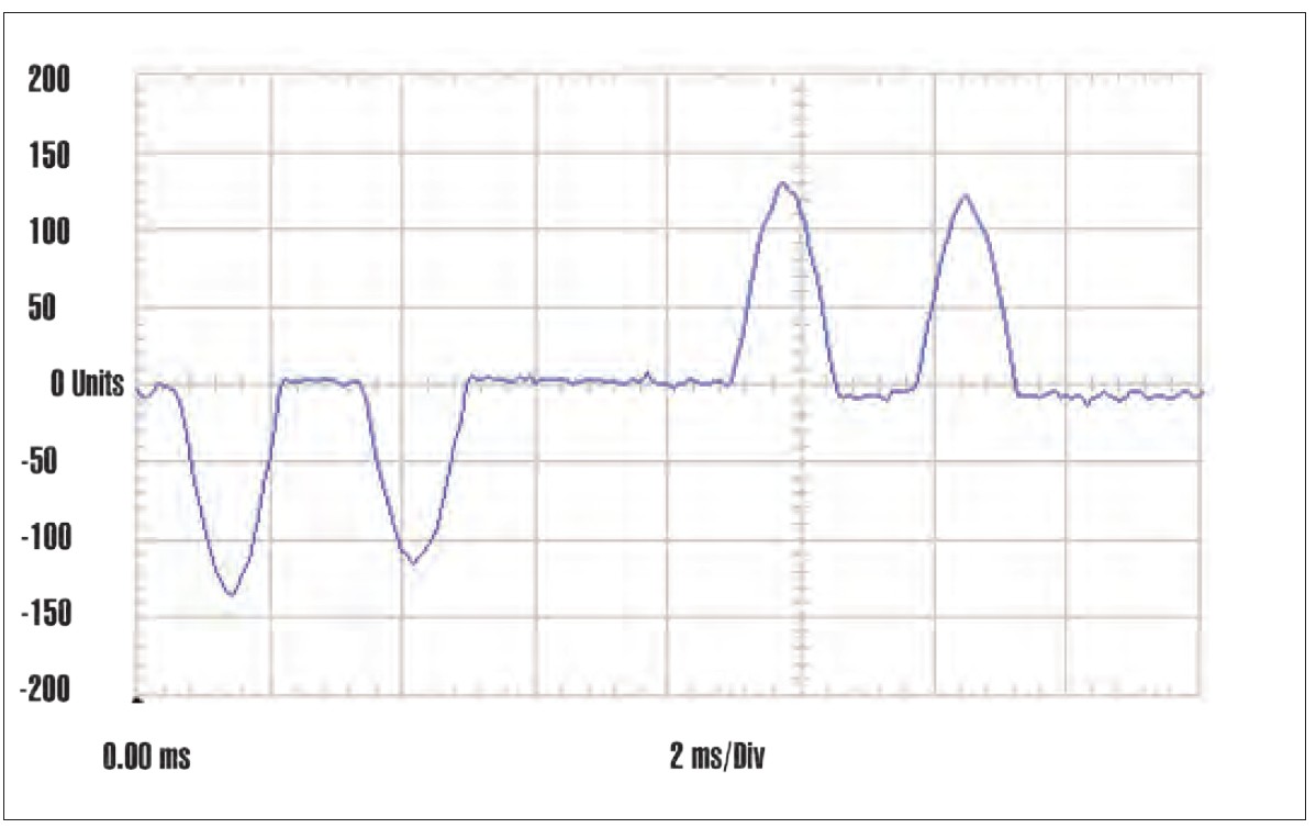 Fig. 1. Input current of 15 HP, 6-pulse ASD on a stiff utility source. THDi = 108% — the characteristic sharp double-pulse waveform of an unfiltered 6-pulse rectifier. Despite this very high current distortion, the low source impedance produces negligible voltage distortion. Source: Mirus International / EGSA Powerline Q3 2019.[1]
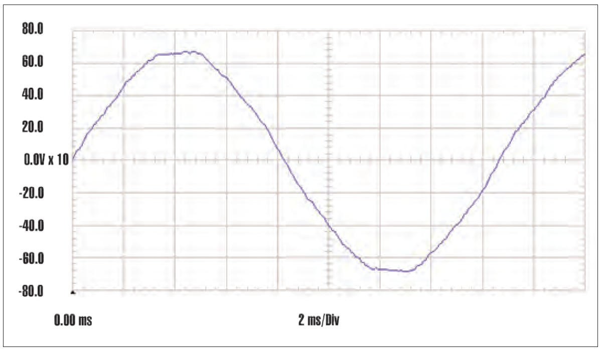 Fig. 2. Input voltage of 15 HP, 6-pulse ASD on a stiff utility source. THDv = 2.2% — the low source impedance absorbs the harmonic currents without significant voltage distortion. The voltage waveform is essentially sinusoidal. Source: Mirus International / EGSA Powerline Q3 2019.[1]
3.2 Weak generator supply — same drive, same load
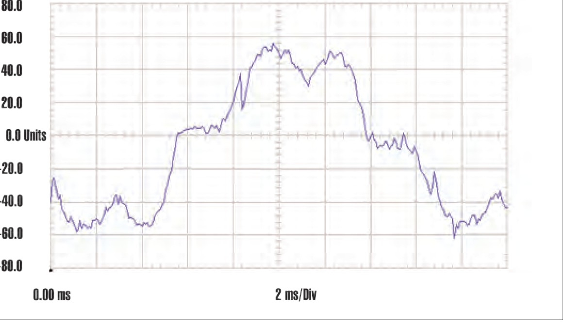 Fig. 3. Input current of the same 15 HP ASD, now fed from a weak generator source. THDi = 25.8% — lower than on the stiff utility source because the high source impedance smooths the current pulses. Source: Mirus International / EGSA Powerline Q3 2019.[1]
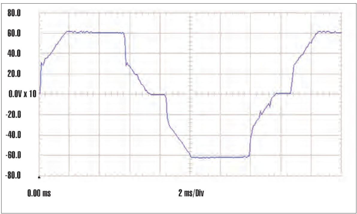 Fig. 4. Input voltage of the same 15 HP ASD on the weak generator source. THDv = 13.8% — severe flat-topping visible. Despite the lower THDi, voltage distortion is catastrophically worse because the harmonic currents flow through the high generator source impedance. Source: Mirus International / EGSA Powerline Q3 2019.[1]
On the generator supply: THDi = 25.8%, THDv = 13.8%.
The current distortion fell by 75% — but voltage distortion increased by more than 6×. The high source impedance of the generator smooths the current pulses (reducing THDi) while simultaneously converting those same harmonic currents into severe voltage distortion (increasing THDv). This is why THDi measured on a generator supply cannot be compared directly to utility-system THDi measurements — the metric changes meaning with the source impedance. Voltage distortion is the consequence that matters for equipment reliability, and on a generator it can be catastrophic even when current distortion appears modest.
04 Wide Spectrum Harmonic Filter: Design and Generator Compatibility
4.1 The WSHF topology
A wide spectrum harmonic filter (WSHF) is a passive series-connected filter using a combination of a blocking element and a tuned filtering element. Unlike tuned passive filters that target specific harmonic orders, a WSHF provides harmonic reduction across a broad frequency range — attenuating all characteristic harmonics of a 6-pulse rectifier (5th, 7th, 11th, 13th) simultaneously. THDi at full load can be reduced to as low as 5% regardless of whether the drive includes an AC or DC reactor.[1]
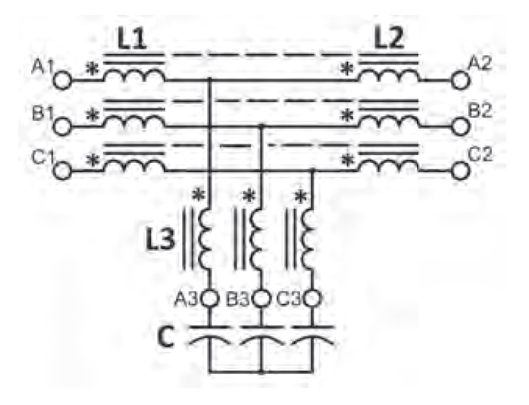
Fig. 5. Wide Spectrum Harmonic Filter schematic. The design combines a blocking element (L1, L2 — multiple windings on a common core exploiting mutual coupling) with a tuned filtering element (L3, C). The resonant frequency as seen from the input terminals is near the 4th harmonic — below the predominant harmonics of 3-phase rectifiers. Source: Mirus International / EGSA Powerline Q3 2019.[1]
4.2 Why low capacitive reactance is critical for generators
The design of the WSHF capacitor bank is particularly important for generator-fed applications. The mutual coupling between the multiple windings on the common core reactor allows the use of a significantly smaller capacitor bank — typically less than 15% reactive power as a percentage of full load rating. This is a critical differentiator from competing passive filter designs.[1]
Many wide spectrum filters feature capacitance values of 30% or greater relative to their kW rating. At light load, when the harmonic filtering demand is low but the capacitive reactive power is still present, these large capacitor banks can cause leading power factor conditions and voltage boost that interfere with generator AVR regulation. Some suppliers address this by switching out the capacitors at light load — which simultaneously eliminates the filter’s harmonic mitigation capability at the load levels where generator stability is most critical. The WSHF’s inherently low capacitive reactance avoids this problem without requiring a switching contactor.
4.3 Upstream harmonic importation protection
In installations where multiple nonlinear loads share a common generator bus, a harmonic filter on one drive must not be overloaded by harmonic currents flowing in from other drives on the same bus. The WSHF design addresses this by placing the resonant frequency (as seen from the input terminals) near the 4th harmonic — below the 5th harmonic that is the dominant characteristic of 3-phase rectifiers. This means harmonic currents from other loads on the bus see a high impedance at the filter input terminals and are blocked from flowing into the filter. The filter protects itself from the network.
05 Case Study: 200 HP Remote Pump — From 500 kW to 350 kW Generator
The case study is a 200 HP (150 kW), 480 V pump at an unmanned remote site in the Midwest USA, supplied by an islanded diesel generator. This is the same application documented in the Plains All-American Pipeline case study earlier in this IPQDF series — the EGSA Powerline article provides the full technical analysis that the commercial case study summarized.[1]
5.1 The failure sequence
The original 176 kW generator caused generator instability and repeated ASD failures. Following the generator manufacturer’s recommendation, a 500 kW generator was installed. This reduced but did not eliminate the ASD operational problems — the harmonic currents were still present, still causing losses, still distorting the voltage. The oversized generator was simply large enough to absorb the consequences without failing catastrophically.
5.2 Three-way simulation: no filter, AC reactor, WSHF
Computer simulation was performed for the 500 kW generator supplying the 200 HP ASD at 90% load under three conditions. The generator subtransient reactance X”d = 11.8%, power factor = 0.8.[1]
| Parameter | No mitigation | 3% AC reactor | WSHF |
|---|---|---|---|
| THDv | 7.6% | 5.4% | 1.7% |
| THDi | 44.7% | 32.0% | 6.6% |
| Current (A) | 198.8 | 191.5 | 180.3 |
| Real power (kW) | 147.2 | 146.9 | 148.3 |
5.3 Field measurements — AC reactor vs. WSHF on the 500 kW generator
Field measurements were taken at a pump flow rate of 240 BPH, controlled by a separate control loop. The comparison between the 3% AC reactor (existing) and the WSHF (installed as replacement) confirmed the simulation results — and revealed an unexpected additional benefit:[1]
| Parameter | 3% AC reactor | WSHF | Improvement |
|---|---|---|---|
| THDv | 6.0% | 2.3% | 62% reduction |
| THDi | 23.7% | 5.7% | 76% reduction |
| Current (A) | 181 | 137 | 24% reduction |
| Real power (kW) | 137.5 | 111.5 | 19% reduction at same flow rate |
5.4 Rightsizing to the 350 kW generator — simulation and field measurement
With THDi below 10%, the generator derating factor dropped from 2–2.5× to 1.4×. The pump now required only 111.5 kW real power — justifying a generator as small as 200 kW by the calculations. The operator, understandably cautious given the history of failures, chose a 350 kW natural gas generator instead, converting from diesel to available flare gas.[1]
| Parameter | Computer simulation (350 kW gen) | Field measurements (350 kW gen) |
|---|---|---|
| THDv | 2.3% | 2.5% |
| THDi | 6.2% | 5.8% |
| Current (A) | 180.6 | 144 |
| Real power (kW) | 148.5 | 117.6 |
| True PF | 0.99 | 0.99 |
Simulation and field measurements agreed closely on THDv and THDi. Both values met IEEE 519 requirements comfortably on the smaller generator.[2] The near-unity True Power Factor (0.99) reflects the WSHF capacitors compensating the motor’s inductive reactive power — reducing generator loading and improving system efficiency.
06 Fuel Consumption and Emissions: Quantifying the Business Case
The fuel and emissions analysis compared three operating scenarios at the same 240 BPH throughput: 500 kW generator with AC reactor (baseline), 500 kW generator with WSHF, and 300 kW generator with WSHF. Diesel cost: $3.80 USD/gallon. CO₂ emission factor: 10.2 kg/gallon. Operation: 24 hrs/day, 7 days/week.[1]
| Parameter | 500 kW + AC reactor | 500 kW + WSHF | 300 kW + WSHF |
|---|---|---|---|
| Load (kW) | 137.5 | 111.5 | 117.2 |
| Load % | 27.4% | 22.2% | 39.2% |
| Fuel rate (gal/hr) | 11.8 | 10.1 | 7.3 |
| Monthly fuel (gal/mo) | 8,496 | 7,272 | 5,256 |
| Monthly fuel cost (USD) | $32,285 | $27,634 | $19,973 |
| Monthly fuel savings | — | $4,651 (14.4%) | $12,312 (38.1%) |
| Monthly CO₂ (kg) | 86,400 | 74,160 | 53,280 |
| Monthly CO₂ reduction (kg) | — | 12,240 | 33,120 |
Level 2 — Rightsize to 300 kW generator + WSHF: $12,312/month fuel savings, 33,120 kg CO₂/month reduction (equivalent to removing 84 automobiles from service). The generator rightsizing amplifies the fuel savings far beyond what the filter alone achieves.
The 500 kW generator running at 22–27% load is operating in its least efficient region. A correctly sized generator at 39% load not only uses less fuel in absolute terms — it uses less fuel per kWh delivered because it operates at a higher load fraction where diesel engine efficiency is better. The two effects compound: smaller engine, better efficiency per unit of output.
07 PQ Perspective: The Complete Engineering Argument
7.1 Why this article belongs in a PQ series
This EGSA Powerline article by Hoevenaars and McGraw is the most technically complete treatment of the generator-harmonics-rightsizing relationship in this IPQDF series. It provides what the commercial case studies did not: the underlying generator physics (X”d, AVR sensitivity, skin effect), the source impedance theory explaining the THDi/THDv relationship, the simulation methodology, the data tables, and the emissions quantification — all in a single document aimed at the generator industry audience.
From a utility power quality background, the arguments here are familiar but the framing is different. The utility engineer thinks about harmonics as a network pollution problem — one customer’s injected harmonics affecting neighbouring customers. The generator engineer thinks about harmonics as a capacity and efficiency problem — the generator can’t deliver its rated output because harmonics consume capacity and increase losses. Both framings are correct. The solution — reduce harmonic current at source — is the same in both cases.
7.2 The derating factor transition at 10% THDi
The specific threshold cited by generator manufacturers — reduce THDi below 10% and the derating factor drops from 2–2.5× to 1.4× — is the engineering pivot point around which the entire rightsizing argument turns. The Lineator AUHF and Lineator WSHF reliably achieve 5–8% THDi at full load, comfortably below this threshold. A 3% AC reactor typically achieves 20–30% THDi — above the threshold, so the 2× derating still applies. This single performance distinction is what makes a wide spectrum passive filter the enabling technology for generator rightsizing.
7.3 Simulation + field measurement — the right methodology
The analysis in this article follows the same methodology demonstrated across the Mirus case study series: harmonic simulation before installation to confirm the solution, field measurement after installation to verify performance. The close agreement between simulation and field measurement on THDv and THDi (within 0.2–0.4 percentage points) validates the simulation model and the approach. The unexpected discrepancy on real power — field measurements consistently showing lower power consumption than simulation — is acknowledged honestly and attributed to physical effects (lower insertion loss, improved ASD efficiency) that the simulation software did not model. This kind of transparency about simulation limitations is exactly what a credible engineering analysis should contain.
References
- [1] T. Hoevenaars, P.Eng. and M. McGraw, “Generators and Nonlinear Loads — Harmonic Mitigation Eliminates Oversizing Requirement,” EGSA Powerline, Q3 2019, pp. 17–23. Electrical Generating Systems Association, Boca Raton, FL. Mirus International Inc., Brampton, Ontario, Canada.
- [2] IEEE Std 519-2022, “IEEE Standard for Harmonic Control in Electric Power Systems,” IEEE, New York, NY, 2022.