
Harmonic Mitigation for a Generator-Fed Motor Control Centre: Natural Gas Sweetening Plant — Mirus International
| Location | British Columbia, Canada |
| Application | Natural gas sweetening plant — amine process cooling fans |
| MCCs | 8 Motor Control Centres, each exclusively loaded with VSDs |
| Drive mix per MCC | 7 drives: 1×40 HP, 4×50 HP, 2×60 HP (480 V) |
| Total drives | 56 adjustable frequency drives across 8 MCCs |
| Supply | On-site turbine generators — fully islanded, no utility connection |
| Harmonic filter | Mirus Lineator AUHF — one per MCC |
| Pre-filter THDv (predicted) | > 16.5% — THDi up to 40% |
| Post-filter (measured) | THDv 1.9% — THDi 5.7% at near full load |
01 Operating Context: Sour Gas Processing and Why Power Quality Is Safety-Critical
A natural gas processing and transportation company in British Columbia operates a natural gas sweetening plant — a facility that removes poisonous hydrogen sulfide (H₂S) from sour gas before it can be safely transported in pipelines. The removal process uses an aqueous amine solution that absorbs H₂S from the gas stream. The amine liquid must be maintained at a carefully controlled temperature throughout the process: too warm and absorption efficiency drops; too cool and the process stalls.[1]
Temperature control is accomplished by cooling fans driven by adjustable frequency drives (AFDs). Each of eight process trains — called amine trains — has a dedicated Motor Control Centre containing seven 480 V drives: one 40 HP, four 50 HP, and two 60 HP units. All eight MCCs are supplied by on-site turbine generators. There is no utility grid connection.
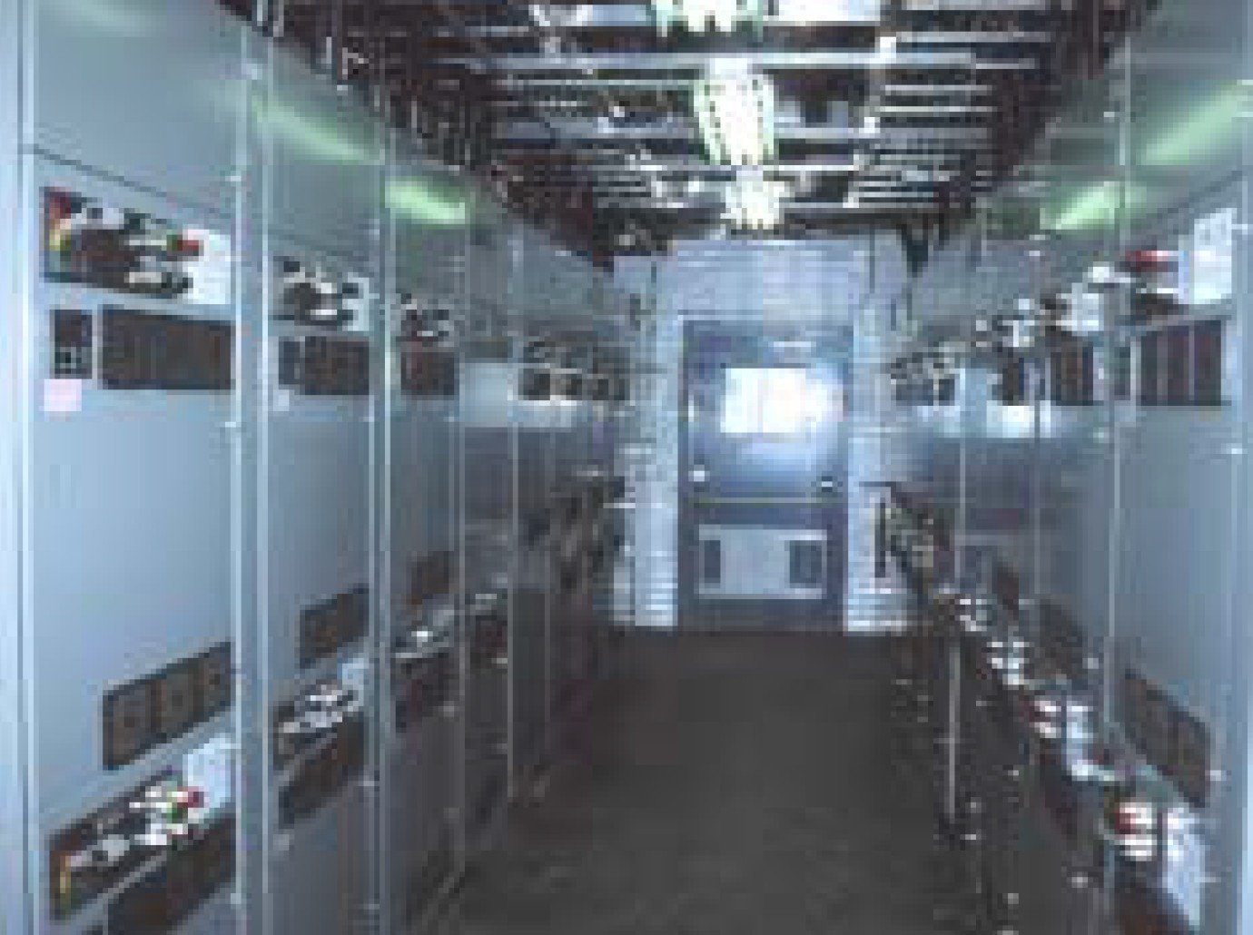
Fig. 1. Motor Control Centre installation at the natural gas sweetening plant, British Columbia. Eight MCCs, each exclusively loaded with seven adjustable frequency drives. Source: Mirus International.[1]
02 The Generator-Fed MCC Problem: Why Standard Solutions Were Ruled Out
2.1 The harmonic loading picture
Eight MCCs, each with seven 6-pulse VSD loads, connected to a common turbine generator bus. Without harmonic mitigation, the predicted Total Harmonic Voltage Distortion on the 480 V switchgear supplying the MCCs exceeded 16.5%, with current distortion as high as 40%.[1] These are not borderline numbers — they represent a system that would be in severe harmonic stress from the first day of operation.
The source of the problem is familiar from previous case studies in this series: turbine generators have high source impedance relative to a utility grid. The same harmonic currents that would produce modest THDv on a utility bus produce dramatically higher THDv on a generator bus. With 56 drives all drawing harmonic current through the same generator source impedance, the cumulative effect was predicted to be severe.
2.2 Why each conventional solution was rejected
The project engineer, Dave Challoner, systematically evaluated the available mitigation options and found each unsuitable for this specific application:[1]
- Line reactors — inadequate harmonic attenuation for a high-impedance generator source. A line reactor reduces harmonic current by adding series impedance, but on a generator-fed system the source impedance is already high, and the additional reactor impedance causes unacceptable voltage drop at the drive terminals without achieving meaningful THDv reduction at the bus level.
- 12- and 18-pulse solutions — would require a phase-shifting transformer per drive or per MCC. With 56 small drives ranging from 40 to 60 HP, the cost of 56 or 8 phase-shifting transformers made this option economically impractical. Multi-pulse solutions scale poorly to installations with many small drives.
- Tuned passive filters — require knowledge of the complete harmonic environment at the point of application. The harmonic contribution from the rest of the generator-fed power system was difficult to characterize, making accurate sizing impossible. An incorrectly tuned filter on a generator-fed system can create resonance that amplifies specific harmonic orders rather than attenuating them.
- Active filters — uncertainty about long-term reliability of power electronic active filter technology in a continuous-duty, safety-critical process environment. Active filters require more maintenance than passive solutions and their failure modes can be more disruptive.
03 Filter Selection: One Lineator per MCC
3.1 Why the Lineator AUHF was chosen
The Lineator AUHF (Advanced Universal Harmonic Filter) was selected on the recommendation of the VSD supplier, and confirmed by Dave Challoner based on three specific attributes required for this application:[1]
- Premium harmonic attenuation — wide-spectrum reduction of the full harmonic profile generated by 6-pulse drives, not just specific harmonic orders
- Reliable passive design — no active power electronics, no control system, no software. In a continuous-duty safety-critical process environment, passive filter simplicity directly translates to reliability and low maintenance burden
- System independence — the filter performs to specification regardless of the harmonic content from other loads on the generator bus, without requiring detailed knowledge of the external harmonic environment
3.2 The MCC-level application strategy
Rather than applying one filter per drive — which would have required 56 units — a single Lineator was applied to each MCC line-up, filtering all seven drives in that MCC simultaneously. This approach works because the Lineator is sized to the aggregate load of the MCC, not to individual drives. The result was eight filters rather than 56, with significant savings in cost, installation complexity, and panel space.[1]
04 Results: Performance That Exceeded Predictions
Post-installation measurements at near full load confirmed that the Lineator AUHF exceeded both the project target and the IEEE 519 guideline limits:[1]
The THDv result of 1.9% is particularly notable — it is less than half the 5% project target and well below the IEEE 519 limit applicable to this system.[2] A THDv below 2% on a generator-fed system with 56 VSD loads represents excellent filter performance. The THDi of 5.7% similarly exceeded the 8% target.
05 The Power Quality Perspective: What This Case Study Illustrates
5.1 The filter selection methodology — elimination by application requirements
This case study is a good example of filter technology selection by systematic elimination based on application-specific constraints. The constraints were: generator supply (ruling out line reactors as insufficient and tuned filters as too risky), many small drives (ruling out multi-pulse as too costly), safety-critical continuous duty (ruling out active filters as insufficiently proven). The process of elimination led directly to the wide-spectrum passive filter — the only technology that satisfied all constraints simultaneously.
This methodology — define constraints first, match technology second — is more reliable than starting with a preferred solution and finding reasons to apply it. It also produces better documentation of the engineering rationale, which is relevant when justifying capital expenditure to project management.
5.2 MCC-level vs. drive-level filtering — when each is appropriate
The decision to filter at the MCC level rather than per drive is valid when the MCC load is predominantly or exclusively VSD loads. In this case, all seven drives per MCC were adjustable frequency drives — 100% non-linear load. Under these conditions, MCC-level filtering is both effective and economical.
The calculus changes when an MCC contains a mix of VSD and linear loads (direct-on-line motors, resistive heaters, transformers). In that case, the linear loads do not generate harmonics but they do consume reactive power, which alters the effective load seen by the filter. A filter sized for the full MCC load including linear loads may be oversized for the harmonic source. Per-drive filtering or careful aggregate sizing accounting for load mix is then required. The natural gas sweetening plant application avoided this complexity by specifying MCC loads that were 100% drives — a fortunate alignment of process requirements and power quality engineering.
5.3 The generator-fed pattern — a recurring theme
This is the third consecutive case study in this series involving a generator-fed islanded system: the Plains All-American pipeline station (diesel generator, single VSD), the offshore service vessel (multiple generators, DC propulsion drives), and now a turbine-generator-fed plant with 56 drives across 8 MCCs. The pattern is consistent: harmonic problems that would be manageable on a utility grid become critical on a generator-fed system, and the solution in every case requires a filter technology that accounts for the high source impedance and the instability risk of the generator voltage regulator.
The next technical article in this series will examine the 6-pulse rectifier from the opposite direction — not as a harmonic source polluting the network, but as a victim of poor supply voltage quality. Understanding how network-side PQ problems degrade drive performance completes the picture of the bidirectional relationship between drives and their power supply.
References
- [1] Mirus International Inc., “Case Study: Natural Gas Sweetening Plant,” Application Case Study, Mississauga, Ontario, Canada. Available: mirusinternational.com
- [2] IEEE Std 519-2022, “IEEE Standard for Harmonic Control in Electric Power Systems,” IEEE, New York, NY, 2022.