
Marine Duty Harmonic Mitigation Saves an Offshore Service Vessel Program — Mirus International
| Application | Offshore supply and service vessel — DC electric propulsion |
| Drives | Four 3,000 HP DC propulsion drives + one 1,500 HP retractable bow thruster DC drive |
| Distribution | 600 V / 480 V vessel power system, multiple generators |
| Operating mode | Dynamic Positioning (DP) — safety-critical, zero tolerance for instability |
| Pre-filter THDv | Up to 20.89% — exceeded all standards, caused equipment failures |
| Harmonic filter | Mirus MOS Lineator Type T (Marine and Offshore Specific) |
| Post-filter THDv | < 8% under all operating conditions — ABS compliant |
| Certification body | American Bureau of Shipping (ABS) |
01 Operating Context: A Vessel That Could Not Go to Work
An offshore supply and service vessel equipped with DC electric propulsion was purchased and upgraded to expand its work scope for the offshore oil and gas industry. The upgrades included enhanced navigation systems, increased-capacity Remote Operated Vehicle (ROV) equipment, and upgraded crane and lift systems. The intent was straightforward: more capable vessel, more revenue-generating contracts.[1]
The result was the opposite. The new equipment proved far more sensitive to voltage distortion than the original systems. During sea trials, voltage harmonic distortion levels exceeded 20% while operating in Dynamic Positioning (DP) mode — the precision station-keeping capability that offshore operators require for work near drill rigs and production platforms. Failures cascaded: navigation systems, crane controls, and ROV equipment all experienced operational problems and component failures. The vessel could not pass sea trials and could not accept offshore contracts.[1]
The vessel predated the current American Bureau of Shipping (ABS) harmonic guidelines and was grandfathered under the older standard. When the upgrade was specified, harmonic compliance was not a design requirement. Only after the failures during sea trials was harmonic mitigation examined as a prerequisite for putting the vessel into service.[1]
02 Why the Existing Mitigation Failed
The vessel was not without harmonic mitigation — it had an existing scheme consisting of phase-shifting transformers operating in parallel with impedance-matched inductors. This is a pseudo multi-pulse arrangement: by phase-shifting the supply to individual drive groups, the intent is to cause the harmonic currents from different groups to cancel in the common supply bus.
The scheme failed to reduce voltage distortion to acceptable levels, and in retrospect this was predictable. Phase-shifted pseudo multi-pulse strategies rely on the harmonic currents from the individual drive groups being equal in magnitude and opposite in phase at the cancellation point. This works reasonably well for PWM-type ASDs with consistent harmonic signatures. It does not work for thyristor-based DC drives.[1]
The combination of variable harmonic content across the five DC drives operating simultaneously at different loads, plus commutation notching, produced the 20%+ THDv measured during sea trials. The existing mitigation was not merely undersized — it was the wrong technology for the application.
03 DC Drives and Commutation Notching: The Mechanism Behind the Failures
3.1 How thyristor commutation creates voltage notches
A thyristor DC drive rectifies AC supply voltage to produce a controlled DC bus. At each commutation event — when conduction transfers from one thyristor to the next — there is a brief period during which two phases of the AC supply are effectively short-circuited through the conducting thyristors. The supply voltage at the drive input collapses to near zero for the duration of the commutation overlap angle. This is a voltage notch.[2]
Voltage notches propagate back into the supply network and appear at every point of common coupling on the same bus. Their severity depends on source impedance — the higher the impedance, the deeper and wider the notch. On a vessel power system with a relatively high source impedance (generators rather than a utility grid), notches are severe and affect all connected equipment simultaneously.
3.2 Why notches cause equipment failures
Voltage notches are high-frequency, high-amplitude disturbances. Digital control systems — navigation computers, crane PLC controllers, ROV drive electronics — sample the supply voltage for synchronization and timing. A voltage notch at the wrong moment can be interpreted as a zero-crossing, causing timing errors, false triggers, or outright fault trips. This is the failure mode that was disabling crane controls and ROV equipment on this vessel: not thermal damage from sustained harmonics, but control system disruption from transient notching.[1]
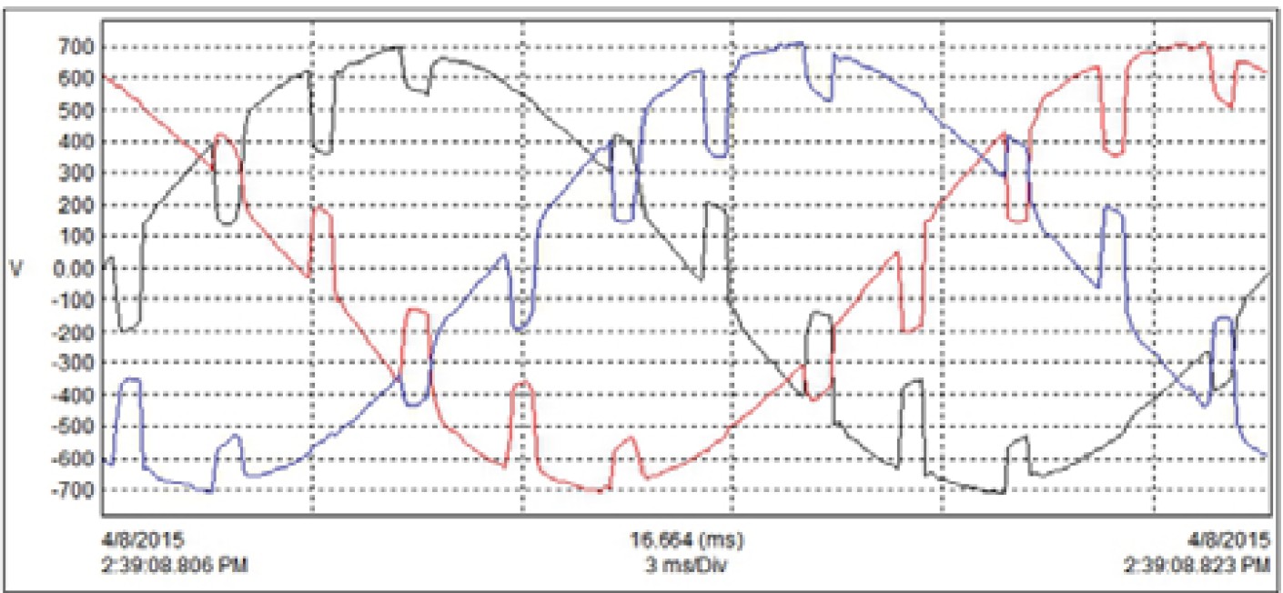
Fig. 1. 480V bus voltage waveform in worst-case conditions — two generators, 100% propulsion speed, bus-tie open. THDv = 20.89%. The severe waveform distortion and commutation notching are clearly visible. Source: Mirus International.[1]
3.3 The simulation picture — SOLV™ analysis
Before committing to a mitigation strategy, Mirus and NSOEM performed a full system-wide vessel review and used Mirus’ proprietary SOLV™ harmonic simulation software to model the complete vessel electrical system — generators, distribution transformers, DC drives at various operating points, and the proposed filter configuration. The simulation workflow had two stages:[1]
- Pre-filter baseline — simulated THDv at the distribution panel with original equipment: 13% on the port side alone, consistent with field measurements
- Post-filter prediction — simulated THDv with MOS Lineators on each DC drive: 5.8% — well within the ABS 8% limit
The close agreement between initial simulation and field-measured pre-filter condition validated the software model. This gave confidence that the post-filter simulation result was reliable before any hardware was ordered or installed.
04 Solution: MOS Lineator — Filter Design for Marine Duty
4.1 Why a marine-specific filter
Standard industrial harmonic filters are not suitable for marine applications. The environment — vibration, salt air, humidity, temperature cycling — demands different construction. Marine classification bodies (ABS, DNV, Lloyd’s Register) impose specific requirements on electrical equipment installed aboard vessels, including harmonic filters.[3] The Mirus MOS (Marine and Offshore Specific) Lineator was developed to meet these requirements while maintaining the harmonic mitigation performance of the standard Lineator AUHF.[1]
4.2 Key filter selection criteria for this application
- Wide-spectrum harmonic reduction — must attenuate the full, variable harmonic spectrum of thyristor DC drives across all operating points, not just the design-point spectrum
- Commutation notch mitigation — the filter inductance damps notch severity by limiting the rate of current change during commutation overlap
- ABS capacitor bank safety disconnect — per new ABS standards, the filter must automatically disconnect the capacitor bank if a capacitor fault occurs while maintaining harmonic filter operation. The MOS Lineator incorporates this as a standard feature
- Redundant safety monitoring — early-stage protective monitoring with redundant alerts, appropriate for a safety-critical DP vessel
- Compact retrofit envelope — hull and deck penetrations for the retrofit were minimized by the compact filter assembly
4.3 Deployment strategy — staged installation during hurricane season
The sea trial testing and filter deployment took place during the Gulf of Mexico hurricane season. This imposed an unusual constraint: the vessel had to retain propulsion capability at all times in case a storm required repositioning. Filters were therefore connected one set at a time — install, test, verify ABS compliance and operational compatibility, then proceed to the next set. Only when each stage was confirmed did the team move forward.[1]
MOS Lineator Type T units were installed on the line side of each of the four 3,000 HP propulsion DC drives and the 1,500 HP retractable bow thruster DC drive — five filters in total. The existing pseudo phase-shifting transformer and inductor equipment was removed.
05 Results: ABS Compliance Under All Operating Conditions
5.1 Voltage distortion — worst case to compliant
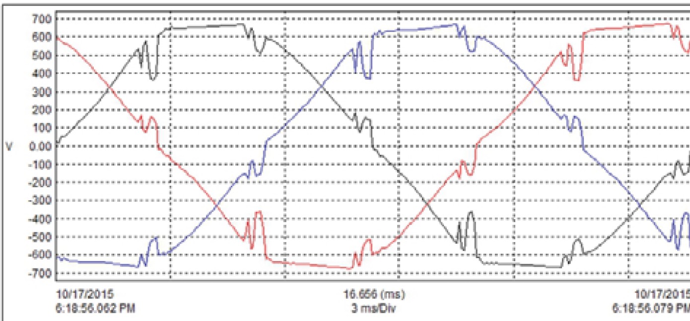
Fig. 2. 480V bus voltage waveform in worst-case Dynamic Positioning operation after MOS Lineator installation. THDv = 7.8% — within the ABS 8% limit. Compare to the 20.89% pre-filter condition in Fig. 1. Source: Mirus International.[1]
The 480V bus THDv dropped from 20.89% (worst-case pre-filter, two generators, 100% speed, bus-tie open) to 7.8% in the equivalent worst-case Dynamic Positioning scenario post-filter — below the ABS 8% limit. Across all tested operating conditions, THDv remained below 8%.[1]
5.2 Bow thruster test data — variable load profile
The 1,500 HP retractable bow thruster was tested across its full speed range with all four generators on line. The results demonstrate the filter’s effectiveness across a wide load range:[1]
| Speed reference | Generators | Bus tie | THDv | THDi | Voltage |
|---|---|---|---|---|---|
| 25% | 4 | Closed | 0.54 – 0.62% | 26 – 30.7% | 603 V |
| 50% | 4 | Closed | 0.7 – 0.9% | 13.83 – 13.93% | 602 V |
| 75% | 4 | Closed | 1.23 – 1.3% | 7.4 – 7.52% | 600 V |
| 100% | 4 | Closed | 0.9 – 0.97% | 5.6 – 5.65% | 599 V |
Note the elevated THDi at 25% speed (26–30.7%). This is characteristic of thyristor DC drives at low firing angles — the current waveform is more distorted at light load. Despite this, voltage distortion remains below 1% at this operating point because the absolute magnitude of the harmonic currents is low at 25% load. This illustrates an important distinction: THDi and THDv are not interchangeable metrics — a high THDi at light load does not necessarily imply a high THDv.
5.3 Worst-case Dynamic Positioning test results
| Operating condition | Generators | THDv | Voltage | Notes |
|---|---|---|---|---|
| Auto DP — all thrusters | All | 2.63 – 2.84% | 479 V | Variable loading |
| Static opposing DP — all thrusters 100% | All | 7.76 – 7.85% | 471 V | Maximum harmonic stress |
| Full speed forward — port and starboard 100% | All | 6.50 – 6.62% | 473 – 478 V | No DDT or TT |
The worst case — static opposing DP with all thrusters at 100% — produced 7.76–7.85% THDv. This is the most severe harmonic loading scenario possible on this vessel: all drives simultaneously at full load, pushing against each other to hold position against wind and current. Even under this condition, the system remained within the ABS 8% limit.[1]
06 The Power Quality Perspective: What This Case Study Illustrates
6.1 Commutation notching — the underappreciated harmonic problem
Most industrial harmonic discussions focus on current THDi and voltage THDv as measured by a power analyzer in steady state. Commutation notching is a different category of disturbance — it is a time-domain transient that occurs at a predictable rate (six times per cycle for a 6-pulse thyristor bridge) but with characteristics that steady-state THD measurement does not fully capture. The notch depth, width, and area are the relevant parameters for assessing equipment compatibility, and these are functions of source impedance and drive firing angle — not just drive size.[2]
IEEE 519 addresses notching in its Table 10.3 limits on notch depth and notch area. ABS has analogous provisions for marine applications. In both cases, the limits exist specifically because control electronics are vulnerable to notch-induced timing errors — exactly the failure mode observed on this vessel.
6.2 THDi vs. THDv — the light-load anomaly
The bow thruster test data makes a point worth emphasizing: at 25% speed, THDi was 26–30% while THDv was below 1%. At 100% speed, THDi had dropped to 5.6–5.65% while THDv was 0.9–0.97%. Both metrics improved with load, but THDi started far higher. This is not a paradox — it is a consequence of how THD is defined as a percentage of the fundamental.
At light load, the fundamental current is small. The harmonic currents, while small in absolute terms, are a large fraction of a small fundamental — producing high THDi. The same small absolute harmonic currents flow through the source impedance and produce a small absolute voltage distortion — hence low THDv. The practical lesson: evaluating harmonic impact on the network requires looking at THDv and absolute harmonic current magnitudes, not THDi alone.
6.3 Simulation before installation — the right sequence
This case study, like the Plains All-American pipeline case, demonstrates the value of harmonic simulation before filter procurement. The SOLV™ model predicted 5.8% THDv post-filter on the port-side circuit; the field-measured result was 7.8% in the worst-case full-vessel DP scenario — a reasonable agreement given the additional thruster loads not present in the port-side-only simulation. The simulation gave enough confidence to specify the correct filter type and size, avoiding an expensive trial-and-error approach on a working vessel.
6.4 Connection to the IPQDF series
The previous two case studies in this series (ESP sinewave filter, Plains All-American pipeline) dealt with 6-pulse PWM drives and thyristor DC drives respectively, both in land-based islanded systems. This case study extends the picture to marine applications and introduces commutation notching as a failure mechanism distinct from sustained harmonic heating. Together, these three case studies cover the major categories of harmonic problems encountered in generator-fed industrial and marine installations.
The technical articles in this series (Articles 1–3) address the same harmonic phenomena from the theoretical side — current spectra, network interaction, motor effects. The case studies show what happens when those phenomena are left unmitigated in real systems. The gap between theory and consequence is usually measured in failed equipment and lost revenue.
References
- [1] Mirus International Inc., “MOS Lineator Case Study: Marine duty harmonic mitigation saves Offshore Service Vessel program,” Application Case Study, Brampton, Ontario, Canada, 2016. Available: mirusinternational.com/moslineator
- [2] IEEE Std 519-2022, “IEEE Standard for Harmonic Control in Electric Power Systems,” IEEE, New York, NY, 2022. (Section on voltage notching, Table 10.3.)
- [3] American Bureau of Shipping (ABS), “Guidance Notes on Control of Harmonics in Electrical Power Systems,” ABS, Houston, TX.