
Author: Denis Ruest, P.Eng/IPQDF
Skill Level: Advanced DIY (Electrical experience required)
Voltage: 120/240V Split-Phase
System Size: 5kW (kilo Watts)
1. Introduction: Understanding Your Goal
A 5kW solar system is a significant investment that can power most of a medium-sized home. Using 14 panels (rather than 13) creates balanced string configurations—two equal strings of 7 panels each—simplifying wiring, improving electrical balance, and making troubleshooting easier.
Before buying parts, you must decide: Grid-Tied or Off-Grid?
- Grid-Tied: You remain connected to the utility. You can sell power back (Net Metering) but the system shuts down during a grid outage for safety (Anti-Islanding). A 5kW grid-tied system typically produces 20-25 kWh per day, enough to offset average household usage.
- Off-Grid: You are completely independent from the utility. Requires a substantial battery bank (48V @ 200Ah or more). The system runs 24/7 regardless of the grid. A 5kW off-grid system can run refrigerators, lights, electronics, and even small air conditioners or well pumps in cycles.
Disclaimer: Working with electricity is dangerous. Consult a licensed electrician for final connections. Permits are required by your local jurisdiction for systems of this size. This article is for informational purposes and does not replace a licensed professional.
2. Why 14 Panels? The Even Number Advantage
Using 14 panels (two strings of 7) offers significant benefits over 13 panels:
| Feature | 13 Panels (7+6) | 14 Panels (7+7) |
|---|---|---|
| String Balance | Unequal strings | Perfectly balanced |
| Voltage Matching | Different string voltages | Identical string voltages |
| Combiner Box | Requires different fusing | Identical fusing for both strings |
| Performance | One string produces less | Equal production from both |
| Expandability | Awkward configuration | Easy to add pairs later |
| Total Power | ~5.0kW (with 385W panels) | ~5.4kW (with 385W panels) |
With 14 x 385W panels, you get 5,390W—a nice buffer above 5kW that helps on cloudy days without overloading most 5kW inverters (which typically accept up to 6,000W DC input).
3. Tools & Materials Checklist
Tools Required:
- Drill & Impact Driver with hex bits
- Socket Set & Wrenches (metric and standard)
- Wire Strippers/Cutters (10 AWG to 2/0 AWG capable)
- Digital Multimeter with DC voltage capability up to 600V
- PV (Solar) Safety Gloves (insulated)
- Torque Wrench (inch-pounds and foot-pounds)
- Stud Finder (electronic)
- Chalk Line
- Conduit Bender (1/2″ and 3/4″)
- Fish Tape
- Cable Lugs Crimping Tool (hydraulic recommended for battery cables)
Materials for a 5kW System (14 Panels):
Solar Array:
- Solar Panels: 14x 360W-400W panels (total 5.0-5.6kW). Choose high-efficiency monocrystalline panels to minimize roof space.
- Racking System: Aluminum rails, L-feet, mid-clamps, end-clamps, flashing (IronRidge, Unirac, or SnapNrack). Ensure rated for wind/snow loads in your area.
- Grounding: Grounding lugs, WEEB washers, or copper wire.
DC Electrical:
- Combiner Box: Weatherproof enclosure with 2-string capability.
- String Fuses: 15A fuses or breakers for each string (2 required, identical ratings).
- PV Wire: 10 AWG or 8 AWG for panel interconnections, 6 AWG for home run.
- DC Disconnect: 30A or 60A outdoor-rated safety switch.
Inverter:
- Grid-Tied Option: 5kW String Inverter (SMA, SolarEdge, Fronius) or 5kW of Microinverters (Enphase IQ8+). Verify max DC input accommodates ~5.4kW.
- Off-Grid Option: 5kW Split-Phase All-in-One Unit with built-in charge controller (Growatt SPF 5000 ES, MPP Solar LVX6048, Victron MultiPlus-II). Must accept 48V DC input.
AC Electrical:
- AC Breaker Panel: Main panel or sub-panel.
- Double-Pole Breaker: 30A for solar backfeed.
- THHN Wire: 10 AWG copper (color-coded: black, red, white, green).
- AC Disconnect: Outdoor-rated safety switch (if required by code).
Off-Grid Only:
- Battery Bank: 48V Lithium Iron Phosphate (LiFePO4) batteries. Minimum 100Ah (5kWh), Recommended 200Ah (10kWh) for overnight loads. Examples: EG4 LL, Trophy Battery, Pylontech.
- Battery Cables: 2/0 AWG or 4/0 AWG welding cable with lugs.
- Class-T Fuse: 250A or 300A with holder.
- Busbars: Heavy-duty copper busbars for battery connections.
- Battery Rack: Server rack or shelf system.
Consumables:
- Wire nuts / Wago connectors
- Cable ties (UV-resistant for outdoors)
- Conduit (Schedule 40 PVC or EMT)
- Penetration sealant (roofing caulk)
- Electrical tape
- Label maker / UV-resistant labels
4. System Design & Layout (The Paperwork Phase)
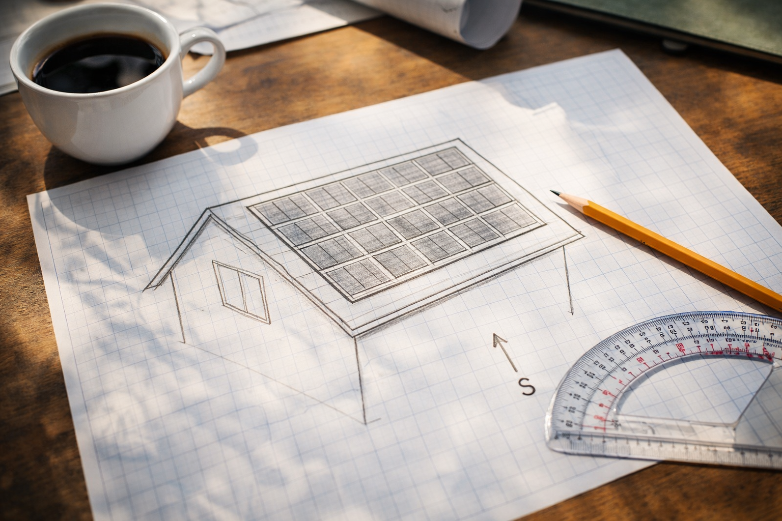
[Image: A sketch on graph paper of a roof with 14 panels arranged in two neat rows of 7, south arrow, and string diagram]
Before lifting a single panel, you must complete the design on paper. This is required for permits and ensures your components work together safely.
Step 4.1: Roof Assessment
- Orientation: South-facing is best in the Northern Hemisphere. Southeast or Southwest will lose 10-15% production.
- Pitch: Most roofs work, but steep pitches (greater than 45°) require special safety equipment.
- Condition: Ensure your roof has at least 10 years of life remaining. Re-roofing after solar installation is expensive.
- Obstructions: Measure distances from chimneys, vents, and skylights. You need 18-36 inches of clearance around the array for fire access (check local codes).
- Layout: With 14 panels, you can arrange them in two rows of 7 (landscape orientation) or seven rows of 2 (portrait orientation). Two rows of 7 is most common.
Step 4.2: String Sizing Calculation (Perfect Balance)
With 14 panels, you create two identical strings of 7 panels each.
- Panel Voltage: Most modern 400W panels have a Voc (open circuit voltage) around 40-45V.
- String A: 7 panels x 45V = 315V (operating) / 365V (max cold temp)
- String B: 7 panels x 45V = 315V (operating) / 365V (max cold temp)
- Total Power: Both strings combine in parallel at the combiner box, producing identical voltage and balanced current.
Critical: Use a string sizing calculator (available on inverter manufacturer websites) with your location’s record low temperature. Cold increases voltage and can destroy your inverter if not calculated correctly. With 7-panel strings, you’ll have plenty of safety margin below the typical 600V max inverter input.
Step 4.3: Production Estimate
A 5.4kW system (14 x 385W) in an area with 5 peak sun hours will generate:
- Daily: 5.4kW x 5hrs x 0.8 (system losses) = 21.6 kWh/day
- Monthly: 21.6 kWh x 30 = 648 kWh/month
- Annually: Varies by season, typically 7,000-9,000 kWh/year
This covers 60-100% of an average home’s usage depending on efficiency.
Step 4.4: Permitting
Visit your local building department with:
- Site plan showing roof dimensions
- Panel layout diagram (14 panels clearly shown)
- Electrical one-line diagram
- Equipment spec sheets
- Structural calculations (if required)
Wait for approval before purchasing equipment or starting installation.
5. Install the Racking (Mounting Hardware)
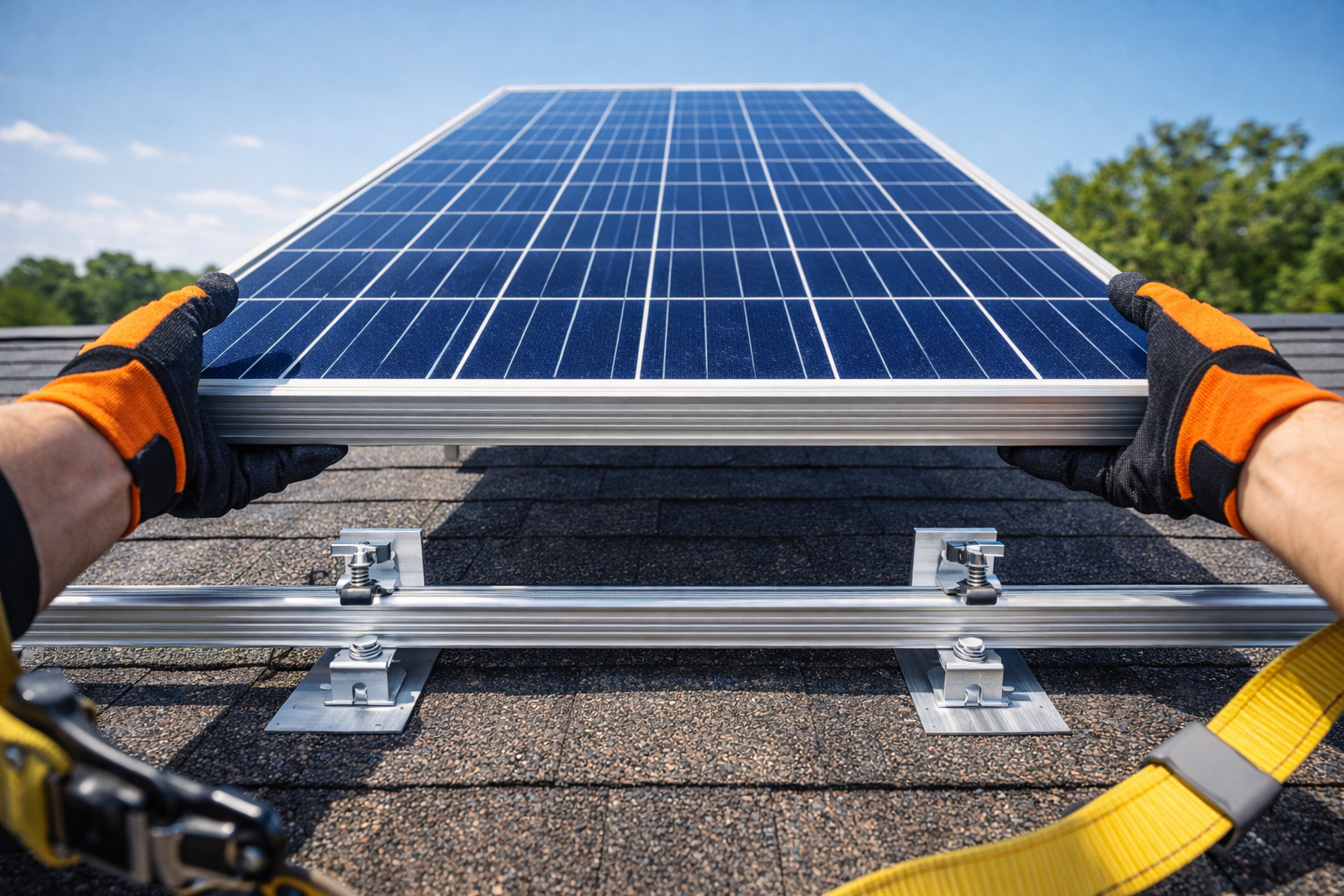
[Image: Flashing installed under lifted shingles with a lag bolt driven into a rafter, safety harness visible]
The racking system is the foundation of your solar array. A 5kW system with 14 panels weighs approximately 650-850 pounds and must withstand wind uplift forces.
Step 5.1: Locate Rafters
- Use an electronic stud finder to locate rafters. Mark them with chalk lines across the roof area.
- Standard rafter spacing is 24″ on center. If your spacing is wider, you need structural reinforcement.
- Mark all rafter locations clearly—you’ll need this for every mounting point.
- For 14 panels in two rows, you’ll need mounting points at each rafter intersection with the rails.
Step 5.2: Install Flashing
- Carefully lift shingles where the mount will go. Use a flat bar to avoid cracking shingles.
- Slide aluminum flashing completely under the shingle, with the top edge under the course above.
- The flashing should have a built-in sealant or you should apply roofing caulk under it.
Step 5.3: Attach L-Feet
- Drill a pilot hole through the flashing and into the rafter center. Use a stop on your drill bit to prevent drilling too deep.
- Insert a lag bolt (typically 3/8″ x 4″ stainless steel) with a built-in washer.
- Tighten firmly but do not over-torque. The goal is to compress the flashing without deforming it.
- Seal the bolt head with additional roofing caulk.
Step 5.4: Install Rails
- Attach aluminum cross rails to the L-feet using T-bolts and caps.
- For 14 panels in two rows of 7, you’ll need two horizontal rails running the full width of the array.
- Ensure rails are perfectly level side-to-side and front-to-back. Use a 4-foot level.
- Join rail sections using internal splices if your run is longer than available rail lengths. Ensure splices are tight and straight.
Safety Tip: Wear a harness with a roof anchor at all times. Falling from a roof can be fatal.
6. Mount the Solar Panels
Step 6.1: Stage Panels Safely
- Hoist panels onto the roof using panel lifters, roof hooks, or handing them up carefully.
- With 14 panels, work systematically—stage panels for one row at a time.
- Place panels face-down on foam pads to protect the glass while you prepare wiring.
Step 6.2: Pre-Wire (Optional but Recommended)
- If accessible, attach MC4 extension cables to the panel junction boxes before mounting.
- This is easier on the ground or with panels flipped over than when they’re mounted.
- For 14 panels, you’ll have 14 positive and 14 negative leads to organize.
Step 6.3: Position Panels
- Start at one corner of the array. Place the first panel onto the rails.
- Work across the row, then start the second row.
- Panels should sit on the rails with the frame resting on the clamps.
Step 6.4: Secure with Clamps
- Mid-Clamps: Used between panels. They clamp the frames of two adjacent panels to the rail. You’ll need approximately 22 mid-clamps.
- End-Clamps: Used at the ends of each rail to secure the last panel. You’ll need 4 end-clamps per rail (8 total).
- Torque all clamps to manufacturer specifications (typically 15-20 ft-lbs). Under-torquing risks panels blowing away; over-torquing can crack the frames.
Step 6.5: Ground the Array
- Use WEEB (Washer Electrical Equipment Bond) clips that pierce the anodized coating on rails and panel frames.
- Alternatively, run a continuous bare copper ground wire bonded to each rail with listed grounding lugs.
- Connect the array ground to the home’s grounding electrode system.
7. Electrical Wiring (DC Side)
[Image: Close-up of MC4 connectors clicking together, then a diagram showing 2 identical strings of 7 panels merging in a combiner box]
With 14 panels, you create two perfectly matched strings of 7 panels each.
Step 7.1: Configure the Strings
- String A (7 panels): Connect positive (+) of panel 1 to negative (-) of panel 2, and so on through all 7 panels. The end will have one free positive and one free negative.
- String B (7 panels): Repeat the process for the remaining 7 panels, following the same pattern.
Step 7.2: Voltage Check
- Before connecting to the inverter, measure each string voltage with a multimeter on a sunny day.
- String A should read approximately 280-320V DC (depending on panel specs and sunlight).
- String B should read identical voltage to String A (within 1-2V).
- Record these values for your records. Matched voltages confirm proper wiring.
Step 7.3: Run Wires to Combiner Box
- Run the positive and negative wires from each string down to the combiner box location (usually near the array edge or on the wall below).
- Use PV wire rated for outdoor exposure and sunlight.
- Label each wire pair clearly: “String A +”, “String A -“, “String B +”, “String B -“.
Step 7.4: Install Combiner Box
- Mount the weatherproof combiner box on the wall near the array or on the roof edge.
- Inside the box, connect each string positive to a 15A fuse or breaker (identical for both strings).
- Connect each string negative to a common negative busbar.
- The combined output goes to a single positive and negative wire (the “home run”).
Step 7.5: Run Home Run to DC Disconnect
- From the combiner box, run 6 AWG PV wire (positive and negative) down to the DC disconnect switch mounted outside near the inverter.
- Use conduit for protection where wires are exposed.
- Label this wire “PV Array Output 5.4kW” at both ends.
8. Mount the Inverter & AC Panel
Step 8.1: Select Location
- Indoors (garage/basement) is ideal for inverter longevity.
- Outdoors requires a NEMA 4X rated inverter.
- Location must be close to the main electrical panel to minimize AC wire runs.
- For off-grid, location must be close to the battery bank (battery cables must be short).
Step 8.2: Install Backboard
- Mount a 4′ x 4′ sheet of 3/4″ plywood on the wall. Paint it with fire-retardant paint if required by code.
- This provides a solid mounting surface and organizes equipment.
Step 8.3: Mount Inverter
- Inverter weight: 5kW units weigh 50-100 pounds. Use lag bolts into studs.
- Maintain manufacturer-specified clearance (typically 6-12 inches on all sides) for airflow.
- Ensure the inverter is level.
Step 8.4: Mount AC Panel
- If using a sub-panel for critical loads (off-grid), mount it next to the inverter.
- If backfeeding the main panel (grid-tied), ensure the main panel has an open double-pole breaker slot.
Step 8.5: Install Disconnects
- Mount the DC disconnect (between combiner box and inverter) within sight of the inverter.
- Mount the AC disconnect (between inverter and main panel) if required by local code.
9. Battery Bank Wiring (Off-Grid Only)
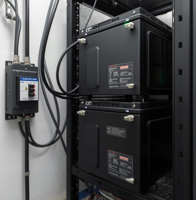
[Image: A rack of blue lithium batteries wired in series-parallel to create 48V, with heavy cables and a Class-T fuse]
A 5kW inverter at 48V draws 104 Amps at full load. This requires serious cabling and safety protection.
Step 9.1: Select Battery Configuration
- 48V System: Most 5kW off-grid inverters require a 48V battery bank.
- Capacity: For a 5kW load to run overnight (say 10 hours at partial load), you need at least 10kWh of storage.
- Typical Setup with 14 Panels: With 5.4kW of solar, you can charge a substantial battery bank. Recommended: 48V @ 200Ah (10kWh) minimum, 48V @ 300Ah (15kWh) ideal.
- Configuration Options:
- 4x 12V 200Ah batteries in series = 48V @ 200Ah (10kWh)
- 8x 12V 200Ah in series-parallel = 48V @ 400Ah (20kWh)
- 3x 48V server rack batteries in parallel = 48V @ 300Ah (15kWh)
Step 9.2: Position Batteries
- Place batteries on a rack or shelf. Never place directly on concrete floor (cold can damage them).
- Ensure adequate ventilation—batteries can off-gas (even lithium in fault conditions) and generate heat.
Step 9.3: Wire Batteries
- Use 2/0 AWG or 4/0 AWG welding cable for all battery interconnections.
- Crimp heavy-duty lugs onto cables using a hydraulic crimper.
- For series connections: Connect positive of battery 1 to negative of battery 2, etc.
- For parallel strings: Connect all positives together on a busbar, all negatives together on a busbar.
Step 9.4: Install Class-T Fuse
- CRITICAL: Install a Class-T fuse within 12 inches of the battery positive terminal.
- Fuse sizing: Inverter max continuous current x 1.25 = fuse size. For 104A x 1.25 = 130A minimum. Most 5kW inverters use 200A-250A fuses to handle surge loads.
- The Class-T fuse protects against short circuits—batteries can deliver thousands of amps in a fault, causing fire or explosion.
Step 9.5: Connect to Inverter
- Run the positive cable from the fuse to the inverter battery positive terminal.
- Run the negative cable directly from the battery negative busbar to the inverter battery negative terminal.
- Torque all connections to manufacturer specifications.
Step 9.6: Install Battery Monitor (Optional)
- Install a shunt-based battery monitor (Victron BMV-712 or similar) to track state of charge accurately.
- This is essential for off-grid living to know how much capacity remains.
10. AC Wiring (Grid-Tied & Off-Grid)
[Image: An electrician wiring a 30A double-pole breaker in a main electrical panel, labeled “Solar”]
Step 10.1: Understand the Math
5,400 Watts at 240 Volts = 22.5 Amps continuous (at full 5.4kW output).
National Electrical Code requires circuits to be sized at 125% of continuous load:
- 22.5A x 1.25 = 28.1A
- Therefore, you need a 30A double-pole breaker (next standard size above 28.1A).
Step 10.2: Wire Gauge Selection
- For a 30A breaker, use 10 AWG copper wire (minimum).
- If the run from inverter to main panel exceeds 100 feet, upgrade to 8 AWG to prevent voltage drop.
- Use color-coded THHN wire: Black (L1), Red (L2), White (Neutral), Green (Ground).
Step 10.3: Off-Grid Connection
- Run L1, L2, Neutral, and Ground from the inverter output to a dedicated “Critical Loads” sub-panel.
- In the sub-panel, install standard 15A and 20A breakers for circuits you want backed up (refrigerator, lights, internet, etc.).
- Transfer those circuits from the main panel to the sub-panel.
Step 10.4: Grid-Tied Connection (Backfeeding)
- Run L1, L2, Neutral, and Ground from the inverter output to the main service panel.
- Install the 30A double-pole breaker in an open slot at the opposite end of the panel from the main breaker (this helps with the 120% rule).
- Connect L1 to one terminal of the breaker, L2 to the other terminal. Connect Neutral to the neutral busbar, Ground to the ground busbar.
- Label the breaker “SOLAR 5.4kW” clearly so future electricians know it’s backfed.
Step 10.5: The 120% Rule (Critical for Grid-Tied)
- Your main panel busbar has a rating (usually 100A, 125A, or 200A).
- The sum of the main breaker and the solar backfeed breaker cannot exceed 120% of the busbar rating.
- Example: 125A busbar x 1.2 = 150A maximum. 100A main + 30A solar = 130A, which is acceptable.
- If your panel can’t accommodate this, you need a “Supply Side Tap” (connection before the main breaker), which requires an electrician.
11. Final Connections & Power-On Sequence
[Image: A person using a multimeter to check voltage at the DC disconnect before turning it on]
Step 11.1: Pre-Power Checks
- Visual Inspection: Check every wire connection. Look for loose strands, nicked insulation, or incorrect routing.
- Polarity Check: Verify positive goes to positive, negative to negative everywhere. Reversed polarity on a charge controller or inverter will destroy it instantly.
- Torque Check: Ensure all terminal screws are torqued to spec. Loose connections cause arcing and fires.
- Voltage Check (DC): Measure voltage at the DC disconnect. Both strings should show identical voltage (within 2V).
- Voltage Check (AC): Ensure main panel is energized and voltage is 120/240V ±5%.
Step 11.2: Turn-On Sequence (Grid-Tied)
- Turn on the AC breaker from the main panel to the inverter (grid power).
- Wait for inverter display to power up and show grid parameters.
- Turn on the DC disconnect from the solar array.
- The inverter should detect solar power, synchronize with the grid (takes 2-5 minutes), and begin exporting.
- Verify display shows “Producing” or “Grid-Tied” mode with positive wattage. With 14 panels, you should see 4.5-5.4kW near solar noon.
Step 11.3: Turn-On Sequence (Off-Grid)
- Ensure all AC loads are turned off.
- Turn on the DC battery breaker or disconnect first.
- Inverter screen should light up. Verify battery voltage reads correctly.
- Turn on the solar DC disconnect.
- The charge controller should activate and begin charging batteries (Bulk mode). Voltage should rise.
- Turn on the inverter AC output breaker.
- Test by turning on a small load (like a light). The inverter should power it.
- Gradually add larger loads to test system response.
Step 11.4: Observe Initial Operation
- Let the system run for 30 minutes. Watch for:
- Unusual noises (buzzing, arcing)
- Overheating components
- Error codes on the display
- Inverter fans cycling properly
- With balanced strings, both should contribute equally—check inverter display for per-string data if available.
12. Monitoring & Performance Testing
[Image: A smartphone screenshot showing a solar monitoring app with 5.4kW production and 26.5 kWh daily total]
Step 12.1: Connect Monitoring
- Most modern inverters have Wi-Fi or Ethernet connectivity.
- Download the manufacturer’s app and create an account.
- Register the inverter using its serial number.
- Connect to your home network and verify data transmission.
Step 12.2: Verify Production
- On a clear day near solar noon, your 5.4kW system should produce 4.6kW – 5.2kW depending on:
- Panel temperature (hot panels produce less)
- Angle relative to sun
- Atmospheric conditions
- If production is significantly lower, check for shading issues or wiring problems.
- Compare the two strings—they should show nearly identical output.
Step 12.3: Daily/Annual Expectations
- Daily: 22-32 kWh depending on season
- Monthly: 660-960 kWh
- Annual: 8,000-11,000 kWh (varies by location)
Step 12.4: Off-Grid Specific Monitoring
- Track battery state of charge daily.
- Note what time batteries reach full charge (indicates array sizing adequacy).
- Note what time batteries reach low charge (indicates if more capacity needed).
- Adjust usage habits if needed to stretch through the night.
13. Labeling & Documentation
[Image: A clean electrical panel with professionally printed labels on every breaker and wire]
Code requires specific labeling for safety:
Required Labels:
- DC Disconnect: “PHOTOVOLTAIC SYSTEM DISCONNECT – 5.4kW DC”
- AC Disconnect: “SOLAR AC DISCONNECT – 5.4kW”
- Backfed Breaker: “SOLAR 5.4kW” (on the breaker itself)
- Main Panel: Warning label stating “THIS EQUIPMENT SUPPLIED BY MULTIPLE SOURCES – SOLAR 5.4kW” (if backfeeding)
- Inverter: Manufacturer label with ratings visible
- Combiner Box: “STRING A (7 PANELS)” and “STRING B (7 PANELS)” on each fuse
- All Conductors: Identify at each termination point with voltage and source
Documentation to Keep:
- Permit approval documents
- Equipment manuals
- One-line diagram with actual wire lengths noted
- Warranty information
- Monitoring login credentials
- Emergency shutdown procedure (post near main panel)
- Panel layout diagram showing which panels belong to which string
14. Common Mistakes to Avoid
Mistake #1: Undersizing Wire
- A 5.4kW system pulls serious current. Using 14 AWG wire for battery connections or long DC runs causes voltage drop and fire risk.
- Solution: Always use voltage drop calculators and follow NEC ampacity tables. With 14 panels, your home run current is higher—use 6 AWG minimum.
Mistake #2: Ignoring Temperature Effects on Voltage
- Cold temperatures increase panel voltage. Panels rated 40V at 25°C can reach 48V at -10°C.
- Solution: Calculate string voltage using the record low temperature for your area. With 7-panel strings, you have good safety margin.
Mistake #3: Mixing Panel Types in Strings
- Panels in series must have the same amperage. Panels in parallel must have the same voltage.
- Solution: Buy identical panels for the entire 14-panel array. Don’t mix old and new.
Mistake #4: Skipping the Battery Fuse (Off-Grid)
- Batteries can deliver thousands of amps in a short circuit. Without a fuse, wires will melt and cause fire.
- Solution: Always install a Class-T fuse within 12 inches of the battery positive terminal.
Mistake #5: Not Torquing Connections
- “Hand tight” is not acceptable for electrical connections. Loose connections arc, overheat, and fail.
- Solution: Use a torque wrench on every lug and terminal. Record torque values.
Mistake #6: Improper Grounding
- Solar arrays can build up static charge and are vulnerable to lightning.
- Solution: Bond all metal parts (rails, panel frames) and connect to the home’s grounding electrode system.
Mistake #7: Forgetting the 120% Rule (Grid-Tied)
- Overloading the main panel busbar is a fire hazard.
- Solution: Calculate busbar rating, main breaker size, and solar breaker size before installing.
Mistake #8: Unbalanced Strings
- With 14 panels, you have the opportunity for perfect balance. Don’t create uneven strings.
- Solution: Keep both strings at 7 panels each for identical voltage and current.
15. When to Call a Professional
While this guide is for DIY enthusiasts, certain tasks require licensed electricians:
- Main Panel Modifications: If you need to replace the main panel or move the main breaker.
- Supply Side Taps: If your panel can’t accommodate the 120% rule, a supply-side connection requires utility involvement and professional installation.
- Service Upgrade: If your main service is too small (e.g., 60A service) to handle solar plus existing loads.
- Utility Meter Socket Work: Anything that requires pulling the meter or modifying the meter socket.
- Final Inspection: Many jurisdictions require a licensed electrician to pull the permit and perform final connections.
16. System Specifications Summary
| Component | Specification |
|---|---|
| System Size | 5.4 kW DC (with 385W panels) |
| Panels | 14x 360W-400W monocrystalline |
| Roof Space Required | ~250-280 sq ft |
| String Configuration | 2 strings of 7 panels (perfectly balanced) |
| String Voltage | Each string: ~315V operating / ~365V max |
| DC Wire (Home Run) | 6 AWG PV wire |
| Inverter Output | 5,000W continuous @ 240V (accepts 5.4kW DC) |
| AC Breaker Size | 30A double-pole |
| AC Wire | 10 AWG (8 AWG for long runs) |
| Battery (Off-Grid) | 48V @ 200Ah minimum (10kWh) |
| Battery Cable (Off-Grid) | 2/0 AWG or 4/0 AWG |
| Battery Fuse (Off-Grid) | Class-T, 200A-250A |
| Daily Production | 22-32 kWh (varies by location) |
17. Conclusion
A 5kW solar system using 14 panels offers the perfect balance of power output and electrical symmetry. With two identical strings of 7 panels each, you get:
- Simpler wiring with identical components
- Better performance with balanced power production
- Easier troubleshooting when both strings behave identically
- More power (5.4kW vs 5.0kW) for minimal additional cost
- Future expansion potential by adding pairs of panels
When properly installed, this system will provide clean energy for 25+ years, reduce or eliminate electric bills, and increase your energy independence.
Final Safety Reminder:
-
Obtain all required permits before starting
-
Work with a partner—never alone on a roof or with high voltage
-
Use lockout/tagout procedures when working on electrical panels
-
When in doubt, consult a licensed electricien.