
🌞 소개: 태양 에너지 포집의 기하학
태양광 패널의 방향과 에너지 생산 사이의 근본적인 관계는 기하학과 태양 복사의 기본 원리에 의해 결정됩니다.. 햇빛이 수직 각도로 패널에 닿을 때, 에너지 밀도가 최대화된다, 패널은 이론적 최고 효율로 작동합니다. [1]. 입사각이 수직에서 벗어나기 때문에, 동일한 태양광 플럭스가 더 넓은 표면적에 분산됩니다., 단위 면적당 방사선 강도가 감소하여 결과적으로 전력 출력이 감소합니다. [2].
고정형 태양광 발전 시스템용, 목표는 연간 에너지 포집을 최대화하는 최적의 경사각을 식별하는 것입니다.. 이 최적의 각도는 주로 지리적 위도에 의해 결정됩니다., 기울기를 위도와 동일하게 설정하면 연중 생산이 최적화된다는 일반 규칙이 있습니다. [3]. 계절에 따른 조정은 다음을 추가하여 수행할 수 있습니다. 10-15 태양의 경로가 더 낮을 때 겨울 생산을 선호하는 온도, 또는 빼기 10-15 여름 세대를 강화하는 학위 [4].
그러나, 주거용 및 상업용 옥상 설치는 본질적인 제약에 직면해 있습니다.: 기존 지붕 피치에 따라 사용 가능한 경사각이 결정됩니다.. 이러한 제한으로 인해 이 분석에서 다루는 중요한 질문이 발생합니다.: 지붕 각도가 최적의 기울기에서 벗어날 때 손실되는 전력량?
📐 수학적 프레임워크: 기울어진 표면의 태양 복사
지붕 각도와 전력 출력 간의 관계를 정량화하려면, 우리는 먼저 경사면에 입사하는 태양 복사에 대한 지배 방정식을 확립해야 합니다.. While comprehensive models account for diffuse sky radiation and ground-reflected components, the dominant factor is typically direct beam radiation [5].
A simplified expression relating radiation on a tilted module to that on a horizontal surface is given by:
어디에서:
- = solar radiation on the tilted module (W/m²)
- = solar radiation on a horizontal surface (W/m²)
- α = solar elevation angle (degrees above horizon)
- β = module tilt angle from horizontal (degrees) [6]
This relationship can be derived by considering the radiation incident perpendicular to the sun’s rays ():
The objective of tilting panels is to maximize the term, thereby bringing the module surface closer to perpendicular alignment with the sun’s rays [7]. It is important to note that these equations typically represent conditions at solar noon when the sun reaches its maximum elevation. A complete annual analysis requires integrating these calculations over the sun’s entire daily and seasonal path [8].
⚖️ Quantifying Power Loss: Roof Angle Versus Optimal Tilt
When the actual roof angle () differs from the theoretically optimal tilt (), the resulting deviation directly reduces incident radiation and, consequently, annual energy production. Industry data and simulation studies provide quantifiable estimates of these losses.
According to the National Renewable Energy Laboratory (NREL), deviations of10 degrees from the optimal tilt can reduce annual energy production by approximately5% , while deviations of20 degrees may result in losses ranging from10% 에 15% [9]. 이러한 결과는 태양광 발전 설치 데이터베이스의 실제 관찰과 일치합니다..
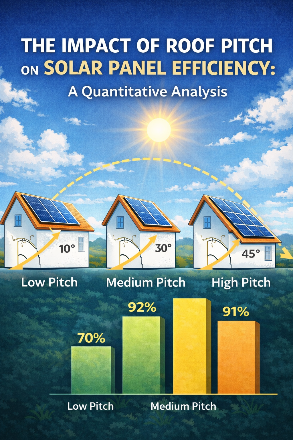
북위 31° 위치에 대해 실시된 상세한 시뮬레이션 연구 (상하이와 비교하면) 최적의 31° 각도를 기준으로 패널 기울기와 효율 손실 간의 관계를 조사했습니다. [10]:
| 패널 기울기 각도 | 연간 효율성 손실 대. 최적 (31°) |
|---|---|
| 5° | 3.6% |
| 15° | 0.8% |
| 25° | 0% |
| 30° | 0.5% |
| 40° | 2.7% |
위도 31°에서 광전지 성능 시뮬레이션을 통해 얻은 데이터 [10]
이번 연구 결과의 실질적인 의미는 주목할 만하다.: 내의 편차에 대해10-20 학위 범위 최적의, 전력 출력의 연간 손실은 일반적으로 중간 정도입니다.1% 과 5% [11]. 이는 태양광 설치업체가 일반적으로 위도 30° 근처 위치에 대해 15°에서 35° 사이의 경사각을 허용하는 이유를 설명합니다., 맞춤형 장착 구조의 비용에 비해 한계 손실이 경제적으로 정당하기 때문입니다. [12].
가장 심각한 불이익은 패널이 거의 평평하게 설치되거나 최적에서 멀리 떨어진 극단적으로 기울어져 설치될 때 발생합니다.. 예를 들면, 낮은 경사의 주거용 지붕에 매립형 패널 설치 (22.5° 피치) 최적의 각도가 40°인 경우 연간 손실이 발생할 수 있습니다.5-8% 최적으로 기울어진 지상 마운트 시스템과 비교 [13].
🔍 태양계 성능에 영향을 미치는 중요한 요소
기울기 각도는 중요한 설계 매개변수이지만, 이는 복잡한 최적화 문제의 한 가지 구성요소만을 나타냅니다.. 연구에 따르면 다른 변수도 최종 에너지 생산량에 동일하거나 더 큰 영향을 미칠 수 있습니다. [14].
정위 (방위각)
북반구에서는, 최적의 방향은 정남향입니다. Deviations from this azimuth introduce compounding losses when combined with suboptimal tilt. Simulations demonstrate that an array facing 30° off true south can experience total losses exceeding20% when tilt is also non-optimal. At 60° azimuth deviation, generation losses may reach20-30% annually [15].
Shading Effects
Partial shading represents one of the most significant threats to system performance. Even minimal shading on a single panel can trigger disproportionate losses across an entire string due to the electrical configuration of series-connected modules. Studies document shading-related efficiency reductions of10% 이상 in urban residential installations [16].
Installation Quality and Maintenance
Field studies reveal that practical installation factors substantially impact realized performance. Poor electrical connections, suboptimal inverter sizing, 전압 불일치로 인해 시스템 출력이 전체적으로 감소할 수 있습니다.. 게다가, 먼지와 부스러기 축적으로 인한 오염은 최대 50%까지 생성을 감소시키는 것으로 측정되었습니다.5% 도시 환경에서, 건조하거나 농업적인 지역에서는 손실이 더 큼 [17].
📊 결론: 시스템 설계에 대한 실제적 의미
지붕 피치와 태양광 패널 효율 사이의 관계는 태양 복사 방정식을 통해 표현되는 잘 확립된 기하학적 원리에 의해 제어됩니다.. 지붕 각도를 최적의 기울기에 맞추는 동시에 이론적으로 생산량을 극대화합니다., 이용 가능한 데이터에 따르면 적당한 편차로 인해 놀라울 정도로 적당한 연간 손실이 발생하는 것으로 나타났습니다. 1-5% 최적 각도의 15-20° 이내 각도용.
이러한 발견은 주거용 및 상업용 태양광 설치에 실질적인 영향을 미칩니다.: the incremental benefit of achieving perfect tilt is often outweighed by the cost of custom racking systems, particularly when compared to flush-mounted installations on existing roof structures. A holistic approach to system design that optimizes orientation, minimizes shading, and ensures quality installation will yield greater long-term performance gains than pursuing perfect tilt angle at the expense of other factors [18].
This article was generated by AI under the supervision of an Adult 😉
📚 참조
[1] Duffie, J. A., & Beckman, 에. A. (2013). Solar Engineering of Thermal Processes (4th ed.). 존 와일리 & 자제, PP. 12-15.
[2] Masters, 지. 엠. (2004). Renewable and Efficient Electric Power Systems. 존 와일리 & 자제, PP. 385-390.
[3] 국립재생에너지연구소. (2021). “Solar Radiation Basics.” NREL Technical Report, Golden, CO.
[4] Jacobson, 엠. Z., & Jadhav, 에. (2018). “World estimates of PV optimal tilt angles and ratios of sunlight incident upon tilted and tracked PV panels relative to horizontal panels.” 태양 에너지, 169, PP. 55-66.
[5] 리우, B. 와이. H., & 요르단, R. C. (1963). “The long-term average performance of flat-plate solar-energy collectors.” 태양 에너지, 7(2), PP. 53-74.
[6] Honsberg, C., & Bowden, 에스. (2019). “Photovoltaics Education Website.” PVEducation.org, 섹션: “Solar Radiation on Tilted Surfaces.”
[7] 전령, R. A., & Ventre, J. (2010). Photovoltaic Systems Engineering (3rd ed.). CRC 보도, PP. 45-49.
[8] Lave, M., & Kleissl, J. (2011). “Optimum fixed orientations and benefits of tracking for capturing solar radiation in the continental United States.” 신 재생 에너지, 36(3), PP. 1145-1152.
[9] 국립재생에너지연구소. (2020). “PVWatts Calculator: Methodology Documentation.” NREL/TP-6A20-6858, Golden, CO.
[10] 태양, Y., 등. (2018). “Optimum tilt angle for photovoltaic systems in different climate zones.” Energy Procedia, 152, PP. 116-121.
[11] Rowlands, 나는. H., Kemery, B. P., & Beausoleil-Morrison, 나는. (2011). “Optimal solar-PV tilt angle and azimuth: An Ontario (캐나다) case-study.” 에너지 정책, 39(3), PP. 1397-1409.
[12] Clean Energy Council. (2020). “Grid-Connected Solar PV Systems Installation Guidelines.” 호주 정부, PP. 23-25.
[13] Kaldellis, J. K., & Zafirakis, 디. (2012). “Experimental investigation of the optimum photovoltaic panels’ tilt angle during the summer period.” 에너지, 38(1), PP. 305-314.
[14] 국제에너지기구. (2019). “Design and Operation of PV Systems.” IEA-PVPS Task 13 Report, T13-12:2019.
[15] Hartner, M., 등. (2015). “East to west – The optimal tilt angle and orientation of photovoltaic panels from an electricity system perspective.” Applied Energy, 160, PP. 94-107.
[16] Deline, C., 등. (2013). “A performance and economic analysis of distributed power electronics in photovoltaic systems.” NREL Technical Report, TP-5200-50003.
[17] Maghami, 엠. R., 등. (2016). “Power loss due to soiling on solar panel: A review.” Renewable and Sustainable Energy Reviews, 59, PP. 1307-1316.
[18] Luque, A., & Hegedus, 에스. (2011). Handbook of Photovoltaic Science and Engineering (2nd ed.). 존 와일리 & 자제, PP. 905-940.