
Auteur: Denis Ruest, P.Eng/IPQDF
Niveau de compétence: Bricolage avancé (Expérience en électricité requise)
Tension: 120/240V Phase divisée
Taille du système: 5kW (kilowatts)
1. Introduction: Comprendre votre objectif
Un système solaire de 5 kW représente un investissement important qui peut alimenter la plupart d'une maison de taille moyenne.. En utilisant14 panneaux (plutôt que 13) crée des configurations de chaînes équilibrées : deux chaînes égales de 7 panneaux chacun - simplifiant le câblage, améliorer l'équilibre électrique, et faciliter le dépannage.
Avant d'acheter des pièces, tu dois décider: Connecté au réseau ou hors réseau?
- Lié à la grille: Vous restez connecté à l'utilitaire. Vous pouvez revendre l'électricité (Facturation nette) mais le système s'arrête lors d'une panne de réseau pour des raisons de sécurité (Anti-îlotage). Un système connecté au réseau de 5 kW produit généralement 20-25 kWh par jour, suffisant pour compenser l’utilisation moyenne des ménages.
- Hors réseau: Vous êtes totalement indépendant de l'utilitaire. Nécessite un parc de batteries important (48V @ 200 Ah ou plus). Le système fonctionne 24/7 quelle que soit la grille. Un système hors réseau de 5 kW peut faire fonctionner des réfrigérateurs, lumières, électronique, et même des petits climatiseurs ou des pompes de puits en cycles.
Désistement: Travailler avec l’électricité est dangereux. Consultez un électricien agréé pour les connexions finales. Des permis sont requis par votre juridiction locale pour les systèmes de cette taille. Cet article est à titre informatif et ne remplace pas un professionnel agréé.
2. Pourquoi 14 Panneaux? L'avantage du nombre pair
En utilisant 14 panneaux (deux chaînes de 7) offre des avantages significatifs par rapport 13 panneaux:
| Fonctionnalité | 13 Panneaux (7+6) | 14 Panneaux (7+7) |
|---|---|---|
| Équilibre des cordes | Cordes inégales | Parfaitement équilibré |
| Correspondance de tension | Différentes tensions de chaîne | Tensions de chaîne identiques |
| Boîte de combinaison | Nécessite une fusion différente | Fusion identique pour les deux chaînes |
| Performance | Une chaîne produit moins | Production égale des deux |
| Extensibilité | Configuration délicate | Facile d'ajouter des paires plus tard |
| Puissance totale | ~5,0 kW (avec panneaux 385W) | ~5,4 kW (avec panneaux 385W) |
Avec 14 x panneaux 385W, tu as5,390DE—un bon tampon au-dessus de 5 kW qui aide par temps nuageux sans surcharger la plupart des onduleurs de 5 kW (qui acceptent généralement jusqu'à 6 000 W d'entrée CC).
3. Outils & Liste de contrôle des matériaux
Outils requis:
- Percer & Tournevis à percussion avec embouts hexagonaux
- Jeu de douilles & Clés (métrique et standard)
- Pinces à dénuder/coupes-fils (10 AWG à 2/0 Compatible AWG)
- Multimètre numérique avec capacité de tension continue jusqu'à 600 V
- PV (Solaire) Gants de sécurité (isolé)
- Clé dynamométrique (pouces-livres et pieds-livres)
- Recherche de goujons (électronique)
- Ligne à craie
- Cintreuse de conduits (1/2″ et 3/4″)
- Ruban à poisson
- Outil de sertissage de cosses de câble (hydraulique recommandé pour les câbles de batterie)
Matériaux pour un système de 5 kW (14 Panneaux):
Panneau solaire:
- Panneaux solaires: 14x panneaux 360W-400W (total 5,0-5,6 kW). Choisissez des panneaux monocristallins à haute efficacité pour minimiser l'espace sur le toit.
- Système de rayonnage: Rails en aluminium, Pieds en L, pinces médianes, pinces d'extrémité, clignotant (Crête de Fer, Unirac, ou SnapNrack). Assurez-vous d'être évalué pour les charges de vent/neige dans votre région.
- Échouage: Cosses de mise à la terre, Rondelles WEEB, ou du fil de cuivre.
Électrique CC:
- Boîte de combinaison: Boîtier résistant aux intempéries avec capacité à 2 cordes.
- Fusibles à chaîne: 15Un fusible ou un disjoncteur pour chaque chaîne (2 requis, notes identiques).
- Fil PV: 10 AWG ou 8 AWG pour les interconnexions de panneaux, 6 AWG pour un coup de circuit.
- Déconnexion CC: 30Un interrupteur de sécurité pour l'extérieur de 60 A ou 60 A.
Onduleur:
- Option liée au réseau: 5Onduleur de chaîne kW (SMA, Bord solaire, Fronius) ou 5 kW de micro-onduleurs (Enphase IQ8+). Vérifiez que l'entrée CC maximale peut contenir environ 5,4 kW.
- Option hors réseau: 5Unité tout-en-un à phase divisée kW avec contrôleur de charge intégré (Growatt SPF 5000 ES, MPP Solaire LVX6048, Victron MultiPlus-II). Doit accepter une entrée 48 V CC.
Électrique CA:
- Panneau de disjoncteur CA: Panneau principal ou sous-panneau.
- Disjoncteur bipolaire: 30A pour le retour solaire.
- Fil THHN: 10 Cuivre AWG (code couleur: noir, rouge, blanc, vert).
- Déconnexion CA: Interrupteur de sécurité pour l'extérieur (si le code l'exige).
Hors réseau uniquement:
- Banque de batteries: 48V Lithium Fer Phosphate (LiFePO4) batteries. Minimum 100 Ah (5kWh), Recommandé 200Ah (10kWh) pour les chargements de nuit. Exemples: EG4 LL, Batterie Trophée, Pylônetech.
- Câbles de batterie: 2/0 AWG ou 4/0 Câble de soudage AWG avec cosses.
- Fusible de classe T: 250A ou 300A avec support.
- Jeux de barres: Barres omnibus en cuivre robustes pour les connexions de batteries.
- Support de batterie: Système de rack ou d'étagère de serveur.
Consommables:
- Serre-fils / Connecteurs Wago
- Attaches de câble (Résistant aux UV pour l'extérieur)
- Conduit (Calendrier 40 PVC ou EMT)
- Scellant de pénétration (calfeutrage de toiture)
- Ruban électrique
- Étiqueteuse / Étiquettes résistantes aux UV
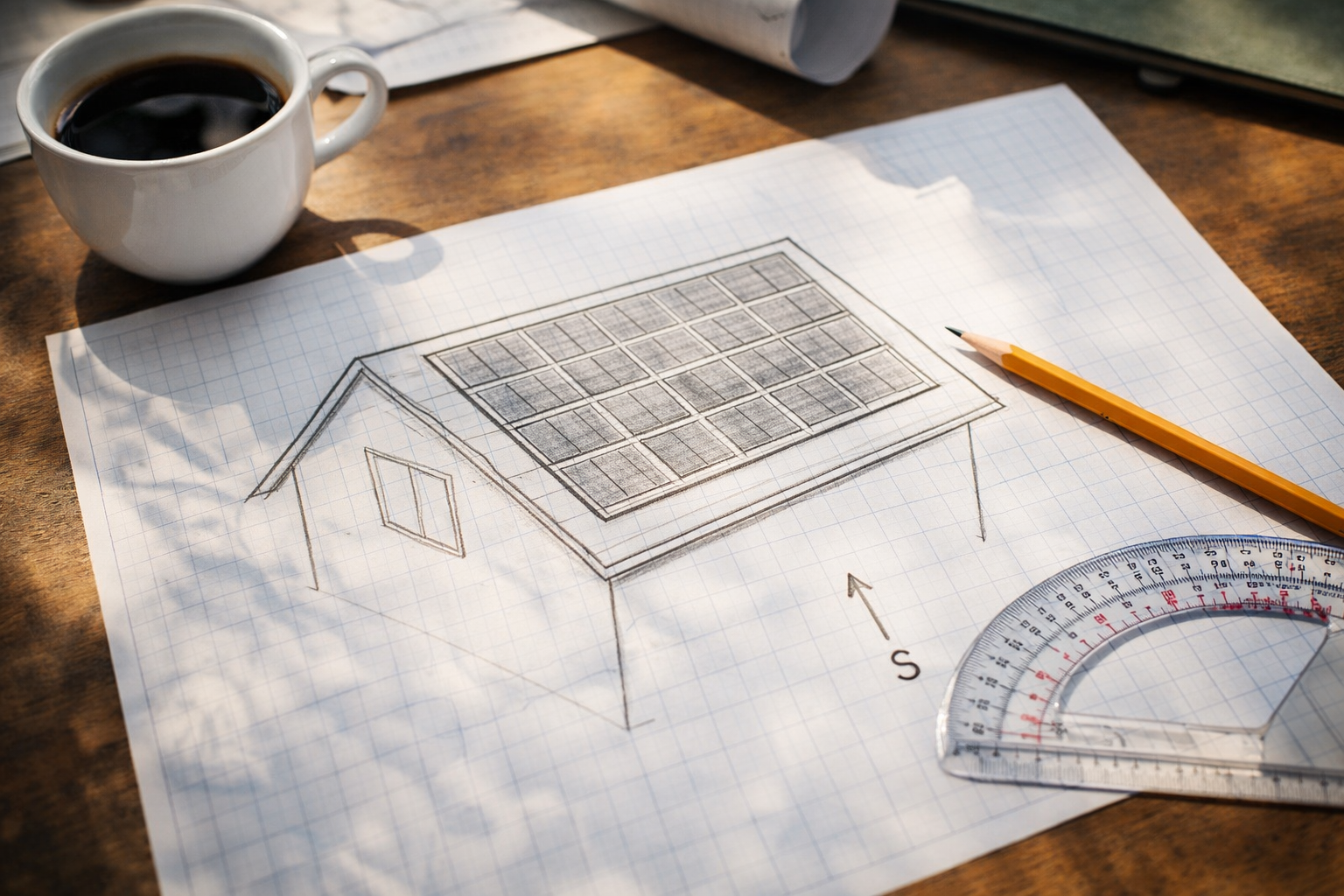
4. Conception du système & Mise en page (La phase de paperasse)
Avant de soulever un seul panneau, vous devez compléter le dessin sur papier. Ceci est requis pour les permis et garantit que vos composants fonctionnent ensemble en toute sécurité..
Étape 4.1: Évaluation du toit
- Orientation: L'orientation sud est la meilleure dans l'hémisphère nord. Le sud-est ou le sud-ouest perdront 10-15% production.
- Pas: La plupart des toits fonctionnent, mais des emplacements raides (supérieur à 45°) nécessitent un équipement de sécurité spécial.
- Condition: Assurez-vous que votre toit a au moins 10 années de vie restantes. Rénover la toiture après une installation solaire coûte cher.
- Obstructions: Mesurer les distances des cheminées, évents, et lucarnes. Vous avez besoin 18-36 pouces d'espace libre autour du réseau pour l'accès au feu (vérifier les codes locaux).
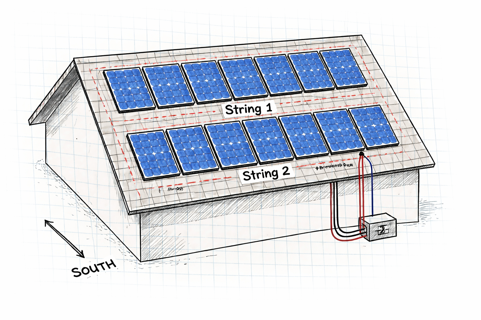
- Mise en page: Avec 14 panneaux, vous pouvez les disposer en deux rangées de 7 (orientation paysage) ou sept rangées de 2 (orientation portrait). Deux rangées de 7 est le plus courant.
Étape 4.2: Calcul de la taille des chaînes (Équilibre parfait)
Avec 14 panneaux, vous créez deux chaînes identiques de 7 panneaux chacun.
- Tension du panneau: La plupart des panneaux modernes de 400 W ont un Voc (tension en circuit ouvert) environ 40-45V.
- Chaîne A: 7 panneaux x 45V = 315V (fonctionnement) / 365En (température froide maximale)
- Chaîne B: 7 panneaux x 45V = 315V (fonctionnement) / 365En (température froide maximale)
- Puissance totale: Les deux chaînes se combinent en parallèle au niveau du boîtier de combinaison, produisant une tension identique et un courant équilibré.
Critique: Utilisez un calculateur de taille de chaîne (disponible sur les sites des fabricants d'onduleurs) avec la température basse record de votre emplacement. Le froid augmente la tension et peut détruire votre onduleur s'il n'est pas calculé correctement. Avec cordes à 7 panneaux, vous aurez une grande marge de sécurité en dessous de l'entrée typique de l'onduleur de 600 V maximum.
Étape 4.3: Estimation de la production
Un système de 5,4 kW (14 x 385W) dans une zone avec 5 les heures de pointe d'ensoleillement généreront:
- Tous les jours: 5.4kW x 5 heures x 0.8 (pertes du système) =21.6 kWh/jour
- Mensuel: 21.6 kWhx 30 =648 kWh/mois
- Annuellement: Varie selon la saison, typiquement 7,000-9,000 kWh/an
Cela couvre 60-100% de l’utilisation moyenne d’une maison en fonction de l’efficacité.
Étape 4.4: Permettre
Visitez votre service de construction local avec:
- Plan du site montrant les dimensions du toit
- Schéma de disposition du panneau (14 panneaux clairement montrés)
- Schéma électrique unifilaire
- Fiches techniques des équipements
- Calculs de structure (si nécessaire)
Attendez l’approbation avant d’acheter du matériel ou de commencer l’installation.
5. Installer le rayonnage (Matériel de montage)
Le système de rayonnage est la base de votre panneau solaire. Un système de 5 kW avec 14 les panneaux pèsent environ 650-850 livres et doit résister aux forces de soulèvement du vent.
Étape 5.1: Localiser les chevrons
- Utilisez un détecteur de montants électronique pour localiser les chevrons. Marquez-les avec des lignes à la craie sur toute la surface du toit..
- L'espacement standard des chevrons est de 24″ au centre. Si votre espacement est plus large, vous avez besoin d'un renforcement structurel.
- Marquez clairement tous les emplacements des chevrons : vous en aurez besoin pour chaque point de montage..
- Pour 14 panneaux sur deux rangées, vous aurez besoin de points de montage à chaque intersection des chevrons avec les rails.
Étape 5.2: Installer le clignotant
- Soulevez soigneusement les bardeaux là où le support ira. Utilisez une barre plate pour éviter de fissurer les bardeaux.
- Glissez complètement le solin en aluminium sous le bardeau., avec le bord supérieur sous le rang au-dessus.
- Le solin doit avoir un scellant intégré ou vous devez appliquer du calfeutrage de toiture en dessous..
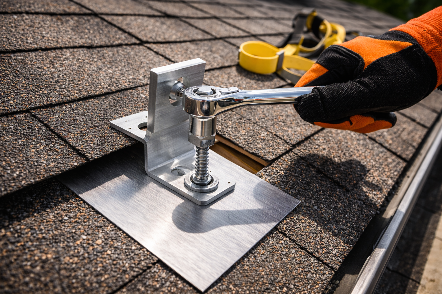
Étape 5.3: Fixez les pieds en L
- Percez un trou pilote à travers le solin et au centre du chevron.. Utilisez une butée sur votre foret pour éviter de percer trop profondément.
- Insérer un tire-fond (généralement 3/8″ x4″ acier inoxydable) avec laveuse intégrée.
- Serrez fermement mais ne serrez pas trop fort. Le but est de comprimer le solin sans le déformer.
- Scellez la tête du boulon avec du calfeutrage de toiture supplémentaire.
Étape 5.4: Installer les rails
- Fixez les traverses en aluminium aux pieds en L à l'aide de boulons en T et de capuchons..
- Pour 14 panneaux en deux rangées de 7, vous aurez besoin de deux rails horizontaux sur toute la largeur du tableau.
- Assurez-vous que les rails sont parfaitement de niveau d’un côté à l’autre et d’avant en arrière. Utilisez un niveau de 4 pieds.
- Joignez les sections de rail à l'aide d'épissures internes si votre parcours est plus long que les longueurs de rail disponibles. Assurez-vous que les épissures sont serrées et droites.
Conseil de sécurité: Portez toujours un harnais avec un ancrage de toit. Tomber d'un toit peut être mortel.
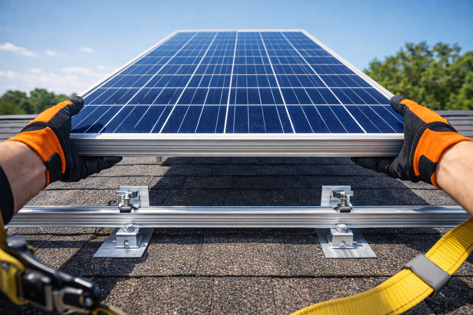
6. Montez les panneaux solaires
Étape 6.1: Panneaux de scène en toute sécurité
- Hisser les panneaux sur le toit à l'aide de lève-panneaux, crochets de toit, ou les remettre soigneusement.
- Avec 14 panneaux, travailler systématiquement : mettre en scène les panneaux pour une rangée à la fois.
- Placez les panneaux face vers le bas sur des coussinets en mousse pour protéger le verre pendant que vous préparez le câblage..
Étape 6.2: Pré-câblage (Facultatif mais recommandé)
- Si accessible, fixez les câbles d'extension MC4 aux boîtes de jonction du panneau avant le montage.
- C'est plus facile au sol ou avec les panneaux retournés que lorsqu'ils sont montés..
- Pour 14 panneaux, tu auras 14 positif et 14 des pistes négatives pour s'organiser.
Étape 6.3: Panneaux de positionnement
- Commencez par un coin du tableau. Placez le premier panneau sur les rails.
- Travailler sur toute la rangée, puis commencez la deuxième rangée.
- Les panneaux doivent reposer sur les rails avec le cadre reposant sur les pinces.
Étape 6.4: Sécurisé avec des pinces
- Pinces intermédiaires: Utilisé entre les panneaux. Ils fixent les cadres de deux panneaux adjacents au rail. Il vous faudra environ 22 pinces médianes.
- Pinces d'extrémité: Utilisé aux extrémités de chaque rail pour fixer le dernier panneau. Vous aurez besoin 4 pinces d'extrémité par rail (8 total).
- Serrez toutes les pinces selon les spécifications du fabricant (typiquement 15-20 pieds-livres). Un sous-serrage risque de faire exploser les panneaux; un couple excessif peut fissurer les cadres.
Étape 6.5: Mettre le tableau à la terre
- Utiliser WEEB (Liaison pour équipement électrique de laveuse) clips qui percent le revêtement anodisé des rails et des cadres de panneaux.
- Alternativement, faire passer un fil de terre continu en cuivre nu relié à chaque rail avec des cosses de mise à la terre répertoriées.
- Connectez la terre du réseau au système d'électrodes de mise à la terre de la maison..
7. Câblage électrique (Côté CC)
[Image: Gros plan des connecteurs MC4 qui s'emboîtent, puis un schéma montrant 2 chaînes identiques de 7 panneaux fusionnant dans une boîte de combinaison]
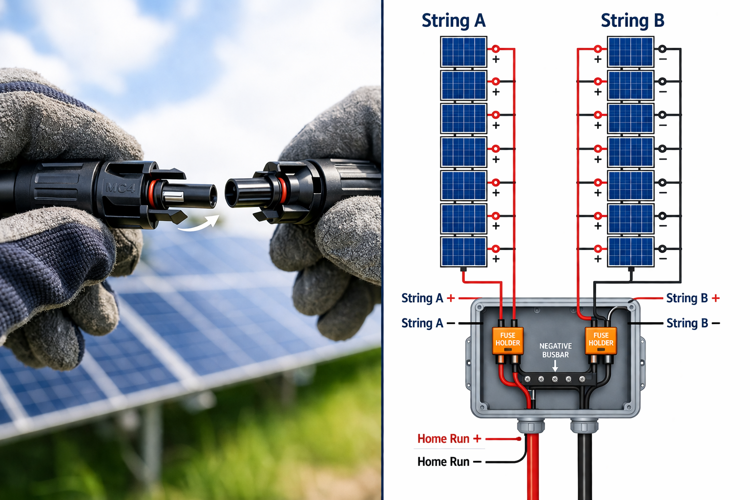
Avec 14 panneaux, vous créez deux chaînes de 7 panneaux chacun.
Étape 7.1: Configurer les chaînes
- Chaîne A (7 panneaux): Connectez positif (+) de panneau 1 au négatif (-) de panneau 2, et ainsi de suite à travers tout 7 panneaux. La fin aura un positif gratuit et un négatif gratuit.
- Chaîne B (7 panneaux): Répétez le processus pour le reste 7 panneaux, suivant le même modèle.
Étape 7.2: Vérification de la tension
- Avant de vous connecter à l'onduleur, mesurer chaque tension de chaîne avec un multimètre par une journée ensoleillée.
- La chaîne A doit indiquer environ 280-320 V CC (en fonction des spécifications du panneau et de la lumière du soleil).
- La chaîne B devrait liretension identique à la chaîne A (dans 1-2V).
- Enregistrez ces valeurs pour vos dossiers. Les tensions correspondantes confirment le câblage correct.
Étape 7.3: Acheminer les fils vers la boîte de combinaison
- Faites passer les fils positifs et négatifs de chaque chaîne jusqu'à l'emplacement du boîtier de combinaison. (généralement près du bord du réseau ou sur le mur en dessous).
- Utilisez un fil PV conçu pour l'exposition extérieure et la lumière du soleil..
- Étiquetez clairement chaque paire de fils: “Chaîne A +”, “Chaîne A -“, “Chaîne B +”, “Chaîne B -“.
Étape 7.4: Installer le boîtier de combinaison
- Montez le boîtier de combinaison résistant aux intempéries sur le mur près de la baie ou sur le bord du toit..
- À l'intérieur de la boîte, connectez chaque chaîne positive à un15Un fusible ou un disjoncteur (identique pour les deux chaînes).
- Connectez chaque chaîne négative à une barre omnibus négative commune.
- La sortie combinée va à un seul fil positif et négatif (la “coup de circuit”).
Étape 7.5: Exécutez Home Run vers DC Disconnect
- De la boîte de combinaison, courir6 AWG fil photovoltaïque (positif et négatif) jusqu'au sectionneur DC monté à l'extérieur, près de l'onduleur..
- Utilisez un conduit pour la protection là où les fils sont exposés.
- Étiquetez ce fil “Sortie du générateur photovoltaïque 5,4 kW” aux deux extrémités.
8. Monter l'onduleur & Panneau CA
Étape 8.1: Sélectionnez un emplacement
- À l'intérieur (garage/sous-sol) est idéal pour la longévité de l’onduleur.
- L'extérieur nécessite un onduleur classé NEMA 4X.
- L'emplacement doit être proche du panneau électrique principal pour minimiser les passages de câbles CA..
- Pour le hors réseau, l'emplacement doit être proche du parc de batteries (les câbles de batterie doivent être courts).
Étape 8.2: Installer le panneau arrière
- Monter un 4′ x4′ feuille de 3/4″ contreplaqué sur le mur. Peignez-le avec de la peinture ignifuge si le code l'exige.
- Cela fournit une surface de montage solide et organise l'équipement.
Étape 8.3: Monter l'onduleur
- Poids de l'onduleur: 5Les unités kW pèsent 50-100 livres. Utilisez des tire-fonds dans les goujons.
- Maintenir le dégagement spécifié par le fabricant (typiquement 6-12 pouces de tous les côtés) pour le flux d'air.
- Assurez-vous que l'onduleur est de niveau.
Étape 8.4: Monter le panneau CA
- Si vous utilisez un sous-panneau pour les charges critiques (hors réseau), montez-le à côté de l'onduleur.
- Si vous rétroalimentez le panneau principal (lié à la grille), assurez-vous que le panneau principal dispose d'un emplacement de disjoncteur bipolaire ouvert.
Étape 8.5: Installer les déconnexions
- Montez le sectionneur DC (entre le boîtier de combinaison et l'onduleur) à portée de vue de l'onduleur.
- Montez le débranchement CA (entre l'onduleur et le panneau principal) si le code local l'exige.
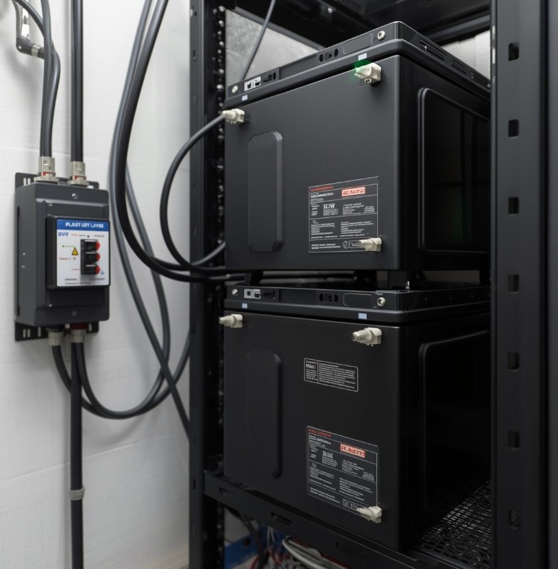
9. Câblage du banc de batteries (Hors réseau uniquement)
Un onduleur de 5 kW à 48 V consomme104 Ampère à pleine charge. Cela nécessite un câblage sérieux et une protection de sécurité.
Étape 9.1: Sélectionnez la configuration de la batterie
- 48Système V: La plupart des onduleurs hors réseau de 5 kW nécessitent un parc de batteries de 48 V.
- Capacité: Pour qu'une charge de 5 kW fonctionne pendant la nuit (dire 10 heures à charge partielle), vous avez besoin d'au moins 10 kWh de stockage.
- Configuration typique avec 14 Panneaux: Avec 5,4 kW d'énergie solaire, vous pouvez charger une batterie importante. Recommandé: 48Dans @ 200Ah (10kWh) minimum, 48V à 300 Ah (15kWh) idéal.
- Options de configuration:
- 4x batteries 12V 200Ah en série = 48V @ 200Ah (10kWh)
- 8x 12V 200Ah en série-parallèle = 48V @ 400Ah (20kWh)
- 3x batteries rack serveur 48V en parallèle = 48V @ 300Ah (15kWh)
Étape 9.2: Positionner les piles
- Placez les piles sur un support ou une étagère. Ne jamais placer directement sur un sol en béton (le froid peut les endommager).
- Assurez une ventilation adéquate : les batteries peuvent dégager des gaz (même le lithium en cas de panne) et générer de la chaleur.
Étape 9.3: Piles filaires
- Utiliser2/0 AWG ou4/0 AWG câble de soudage pour toutes les interconnexions de batterie.
- Sertissez les cosses robustes sur les câbles à l'aide d'une sertisseuse hydraulique.
- Pour les connexions en série: Connectez le positif de la batterie 1 au négatif de la batterie 2, etc.
- Pour les chaînes parallèles: Connectez tous les positifs ensemble sur un jeu de barres, tous les négatifs ensemble sur un jeu de barres.
Étape 9.4: Installer un fusible de classe T
- CRITIQUE: Installez un fusible de classe T à l'intérieur 12 pouces de la borne positive de la batterie.
- Dimensionnement des fusibles: Courant continu maximum de l'onduleur x 1.25 = taille du fusible. Pour 104Ax 1.25 = 130A minimum. La plupart des onduleurs de 5 kW utilisent des fusibles de 200 A à 250 A pour gérer les surtensions..
- Le fusible de classe T protège contre les courts-circuits : les batteries peuvent fournir des milliers d'ampères en cas de défaut, provoquant un incendie ou une explosion.
Étape 9.5: Se connecter à l'onduleur
- Faites passer le câble positif du fusible à la borne positive de la batterie de l'onduleur..
- Faites passer le câble négatif directement de la barre omnibus négative de la batterie à la borne négative de la batterie de l'onduleur..
- Serrez toutes les connexions selon les spécifications du fabricant.
Étape 9.6: Installer le moniteur de batterie (En option)
- Installer un moniteur de batterie basé sur un shunt (Victron BMV-712 ou similaire) pour suivre l'état de charge avec précision.
- Il est essentiel pour la vie hors réseau de savoir quelle capacité reste.
10. Câblage CA (Lié à la grille & Hors réseau)
[Image: Un électricien câble un disjoncteur bipolaire de 30 A dans un panneau électrique principal, étiqueté “Solaire”]
Étape 10.1: Comprendre les mathématiques
5,400 Watts à 240 Volts =22.5 Ampère continu (à pleine puissance de 5,4 kW).
Le Code national de l'électricité exige que les circuits soient dimensionnés à 125% de charge continue:
- 22.5Un x 1.25 =28.1Une
- Donc, tu as besoin d'un30Un disjoncteur bipolaire (prochaine taille standard au-dessus de 28,1A).
Étape 10.2: Sélection du calibre du fil
- Pour un disjoncteur 30A, utiliser10 Fil de cuivre AWG (minimum).
- Si le trajet entre l'onduleur et le panneau principal dépasse 100 pieds, mise à niveau vers8 AWG pour éviter les chutes de tension.
- Utilisez un fil THHN à code couleur: Noir (L1), Rouge (L2), Blanc (Neutre), Vert (Sol).
Étape 10.3: Connexion hors réseau
- Exécuter L1, L2, Neutre, et la masse de la sortie de l'onduleur à un “Charges critiques” sous-panneau.
- Dans le sous-panneau, installez des disjoncteurs standard de 15 A et 20 A pour les circuits que vous souhaitez sauvegarder (réfrigérateur, lumières, internet, etc).
- Transférez ces circuits du panneau principal au sous-panneau.
Étape 10.4: Connexion liée au réseau (Rétro-alimentation)
- Exécuter L1, L2, Neutre, et mise à la terre de la sortie de l'onduleur au panneau de service principal.
- Installez le disjoncteur bipolaire 30A dans une fente ouverte à l'extrémité opposée du panneau au disjoncteur principal. (cela aide avec le 120% règle).
- Connectez L1 à une borne du disjoncteur, L2 vers l'autre borne. Connectez le neutre au jeu de barres neutre, Jeu de barres terre à terre.
- Étiquetez le disjoncteur “SOLAIRE 5,4 kW” clairement pour que les futurs électriciens sachent que c'est rétroalimenté.
Étape 10.5: La 120% Règle (Critique pour les réseaux connectés)
- Le jeu de barres de votre panneau principal a une cote (généralement 100A, 125Une, ou 200A).
- La somme du disjoncteur principal et du disjoncteur de retour solaire ne peut pas dépasser 120% du calibre du jeu de barres.
- Exemple: 125Un jeu de barres x 1.2 = 150A maximum. 100Un plat principal + 30Un solaire = 130A, ce qui est acceptable.
- Si votre panneau ne peut pas gérer cela, tu as besoin d'un “Robinet côté alimentation” (connexion avant le disjoncteur principal), ce qui nécessite un électricien.
11. Connexions finales & Séquence de mise sous tension
[Image: Une personne utilisant un multimètre pour vérifier la tension au niveau du débranchement CC avant de l'allumer]
Étape 11.1: Vérifications avant mise sous tension
- Inspection visuelle: Vérifiez chaque connexion filaire. Recherchez des brins lâches, isolation entaillée, ou un routage incorrect.
- Contrôle de polarité: Vérifier que le positif passe au positif, négatif à négatif partout. Une polarité inversée sur un contrôleur de charge ou un onduleur le détruira instantanément.
- Vérification du couple: Assurez-vous que toutes les vis des bornes sont serrées selon les spécifications.. Des connexions desserrées provoquent des arcs électriques et des incendies.
- Vérification de la tension (DC): Mesurer la tension au niveau du sectionneur CC. Les deux chaînes doivent afficher une tension identique (dans 2V).
- Vérification de la tension (AC): Assurez-vous que le panneau principal est sous tension et que la tension est de 120/240 V ± 5 %.
Étape 11.2: Séquence d'activation (Lié à la grille)
- Allumez le disjoncteur CA du panneau principal à l'onduleur (puissance du réseau).
- Attendez que l'écran de l'onduleur s'allume et affiche les paramètres du réseau..
- Allumez la déconnexion CC du panneau solaire.
- L'onduleur doit détecter l'énergie solaire, synchroniser avec la grille (prend 2-5 procès-verbal), et commencer à exporter.
- Vérifiez que l'écran affiche “Produire” ou “Lié à la grille” mode avec puissance positive. Avec 14 panneaux, vous devriez voir 4,5-5,4 kW vers midi solaire.
Étape 11.3: Séquence d'activation (Hors réseau)
- Assurez-vous que toutes les charges CA sont éteintes.
- Allumez le disjoncteur de batterie CC ou débranchez-le d'abord.
- L'écran de l'onduleur devrait s'allumer. Vérifiez que la tension de la batterie est correcte.
- Allumez le débranchement solaire DC.
- Le contrôleur de charge devrait s'activer et commencer à charger les batteries (Mode groupé). La tension devrait augmenter.
- Allumez le disjoncteur de sortie CA de l'onduleur.
- Testez en allumant une petite charge (comme une lumière). L'onduleur devrait l'alimenter.
- Ajoutez progressivement des charges plus importantes pour tester la réponse du système.
Étape 11.4: Observer le fonctionnement initial
- Laissez le système fonctionner pendant 30 procès-verbal. Surveillez:
- Bruits inhabituels (bourdonnant, arc électrique)
- Composants en surchauffe
- Codes d'erreur sur l'écran
- Les ventilateurs de l'onduleur fonctionnent correctement
- Avec des cordes équilibrées, les deux devraient contribuer de manière égale : vérifiez l'affichage de l'onduleur pour les données par chaîne si disponibles.
12. Surveillance & Tests de performances
[Image: Une capture d'écran d'un smartphone montrant une application de surveillance solaire avec une production de 5,4 kW et 26.5 kWh total journalier]
Étape 12.1: Connecter la surveillance
- La plupart des onduleurs modernes disposent d'une connectivité Wi-Fi ou Ethernet.
- Téléchargez l'application du fabricant et créez un compte.
- Enregistrez l'onduleur en utilisant son numéro de série.
- Connectez-vous à votre réseau domestique et vérifiez la transmission des données.
Étape 12.2: Vérifier la production
- Par temps clair vers midi solaire, votre système de 5,4 kW devrait produire4.6kW – 5.2kW selon:
- Température du panneau (les panneaux chauds produisent moins)
- Angle par rapport au soleil
- Conditions atmosphériques
- Si la production est nettement inférieure, vérifier les problèmes d'ombrage ou les problèmes de câblage.
- Comparez les deux chaînes : elles devraient afficher une sortie presque identique.
Étape 12.3: Attentes quotidiennes/annuelles
- Tous les jours: 22-32 kWh selon saison
- Mensuel: 660-960 kWh
- Annuel: 8,000-11,000 kWh (varie selon l'emplacement)
Étape 12.4: Surveillance spécifique hors réseau
- Suivez quotidiennement l’état de charge de la batterie.
- Notez à quelle heure les batteries atteignent leur pleine charge (indique l'adéquation du dimensionnement du tableau).
- Notez à quelle heure les batteries atteignent une charge faible (indique si plus de capacité est nécessaire).
- Ajustez vos habitudes d'utilisation si nécessaire pour vous étirer toute la nuit.
13. Étiquetage & Documentation
[Image: Un panneau électrique propre avec des étiquettes imprimées par des professionnels sur chaque disjoncteur et fil]
Le code exige un étiquetage spécifique pour des raisons de sécurité:
Étiquettes requises:
- Déconnexion CC: “DÉCONNEXION DU SYSTÈME PHOTOVOLTAÏQUE – 5.4kW CC”
- Déconnexion CA: “DÉCONNEXION SOLAIRE AC – 5.4kW”
- Disjoncteur rétroalimenté: “SOLAIRE 5,4 kW” (sur le disjoncteur lui-même)
- Panneau principal: Étiquette d'avertissement indiquant “CET ÉQUIPEMENT FOURNI PAR PLUSIEURS SOURCES – SOLAIRE 5,4 kW” (en cas de rétroalimentation)
- Onduleur: Étiquette du fabricant avec notes visibles
- Boîte de combinaison: “CHAÎNE A (7 PANNEAUX)” et “CHAÎNE B (7 PANNEAUX)” sur chaque fusible
- Tous les conducteurs: Identifiez à chaque point de terminaison avec la tension et la source
Documentation à conserver:
- Documents d'approbation du permis
- Manuels d'équipement
- Schéma unifilaire avec les longueurs de fil réelles notées
- Informations sur la garantie
- Surveillance des identifiants de connexion
- Procédure d'arrêt d'urgence (poster près du panneau principal)
- Diagramme de disposition des panneaux montrant quels panneaux appartiennent à quelle chaîne
14. Erreurs courantes à éviter
Erreur #1: Fil sous-dimensionné
- Un système de 5,4 kW consomme un courant important. En utilisant 14 Le fil AWG pour les connexions de batterie ou les longs trajets CC provoquent une chute de tension et un risque d'incendie..
- Solution: Utilisez toujours des calculateurs de chute de tension et suivez les tableaux d'intensité admissible NEC.. Avec 14 panneaux, votre courant de course à domicile est plus élevé : utilisez 6 AWG minimum.
Erreur #2: Ignorer les effets de la température sur la tension
- Les températures froides augmentent la tension du panneau. Les panneaux évalués à 40 V à 25 °C peuvent atteindre 48 V à -10 °C.
- Solution: Calculez la tension des chaînes en utilisant la température la plus basse record pour votre région. Avec cordes à 7 panneaux, tu as une bonne marge de sécurité.
Erreur #3: Types de panneaux de mixage dans les chaînes
- Les panneaux en série doivent avoir le même ampérage. Les panneaux en parallèle doivent avoir la même tension.
- Solution: Achetez des panneaux identiques pour l'ensemble de la gamme de 14 panneaux. Ne mélangez pas l'ancien et le nouveau.
Erreur #4: Sauter le fusible de la batterie (Hors réseau)
- Les batteries peuvent fournir des milliers d'ampères lors d'un court-circuit. Sans fusible, les fils fondront et provoqueront un incendie.
- Solution: Installez toujours un fusible de classe T à l'intérieur 12 pouces de la borne positive de la batterie.
Erreur #5: Ne pas serrer les connexions
- “Serré à la main” n'est pas acceptable pour les connexions électriques. Arc de connexions lâches, surchauffer, et échouer.
- Solution: Utilisez une clé dynamométrique sur chaque cosse et borne. Enregistrer les valeurs de couple.
Erreur #6: Mauvaise mise à la terre
- Les panneaux solaires peuvent accumuler une charge statique et sont vulnérables à la foudre.
- Solution: Collez toutes les pièces métalliques (rails, cadres de panneaux) et connectez-vous au système d’électrodes de mise à la terre de la maison.
Erreur #7: Oublier le 120% Règle (Lié à la grille)
- La surcharge du jeu de barres du panneau principal présente un risque d'incendie.
- Solution: Calculer la valeur nominale du jeu de barres, taille du disjoncteur principal, et la taille du disjoncteur solaire avant l'installation.
Erreur #8: Cordes déséquilibrées
- Avec 14 panneaux, vous avez la possibilité d'atteindre un équilibre parfait. Ne créez pas de chaînes inégales.
- Solution: Gardez les deux cordes à 7 panneaux chacun pour une tension et un courant identiques.
15. Quand appeler un professionnel
Bien que ce guide soit destiné aux bricoleurs, certaines tâches nécessitent des électriciens agréés:
- Modifications du panneau principal: Si vous devez remplacer le panneau principal ou déplacer le disjoncteur principal.
- Robinets côté alimentation: Si votre panneau ne peut pas accueillir le 120% règle, une connexion côté alimentation nécessite la participation du service public et une installation professionnelle.
- Mise à niveau du service: Si votre service principal est trop petit (par exemple, 60Un service) pour gérer l'énergie solaire et les charges existantes.
- Travaux de prise de compteur utilitaire: Tout ce qui nécessite de retirer le compteur ou de modifier le socle du compteur.
- Inspection finale: De nombreuses juridictions exigent qu'un électricien agréé retire le permis et effectue les connexions finales..
16. Résumé des spécifications du système
| Composant | Spécification |
|---|---|
| Taille du système | 5.4 kW CC (avec panneaux 385W) |
| Panneaux | 14x 360W-400W monocristallin |
| Espace de toit requis | ~250-280 pieds carrés |
| Configuration de chaîne | 2 chaînes de 7 panneaux (parfaitement équilibré) |
| Tension de chaîne | Chaque chaîne: ~315V fonctionnant / ~365 V maximum |
| Fil CC (Coup de circuit) | 6 Fil PV AWG |
| Sortie de l'onduleur | 5,000W continu à 240 V (accepte 5,4 kW CC) |
| Taille du disjoncteur CA | 30Un bipolaire |
| Fil CA | 10 AWG (8 AWG pour les longues courses) |
| Batterie (Hors réseau) | 48V à 200 Ah minimum (10kWh) |
| Câble de batterie (Hors réseau) | 2/0 AWG ou 4/0 AWG |
| Fusible de batterie (Hors réseau) | Classe T, 200A-250A |
| Production quotidienne | 22-32 kWh (varie selon l'emplacement) |
17. Conclusion
Un système solaire de 5 kW utilisant 14 les panneaux offrent l’équilibre parfait entre puissance de sortie et symétrie électrique. Avec deux chaînes identiques de 7 panneaux chacun, tu as:
- Câblage plus simple avec des composants identiques
- Meilleures performances avec une production d'énergie équilibrée
- Dépannage plus facile quand les deux chaînes se comportent de manière identique
- Plus de puissance (5.4kW contre 5,0 kW) pour un coût supplémentaire minime
- Expansion future potentiel en ajoutant des paires de panneaux
Lorsqu'il est correctement installé, ce système fournira de l'énergie propre pour 25+ ans, réduire ou éliminer les factures d'électricité, et augmentez votre indépendance énergétique.
Dernier rappel de sécurité:
-
Obtenez tous les permis requis avant de commencer
-
Travaillez avec un partenaire, jamais seul sur un toit ou sous haute tension
-
Utiliser des procédures de verrouillage/étiquetage lorsque vous travaillez sur des panneaux électriques
-
En cas de doute, consulter un électricien agréé.