
🌞 Introduction: La géométrie de la capture de l’énergie solaire
La relation fondamentale entre l’orientation d’un panneau solaire et sa production d’énergie est régie par les principes de base de la géométrie et du rayonnement solaire.. Lorsque la lumière du soleil frappe un panneau selon un angle perpendiculaire, la densité énergétique est maximisée, et le panneau fonctionne à son efficacité maximale théorique [1]. Lorsque l'angle d'incidence s'écarte de la perpendiculaire, le même flux solaire est réparti sur une plus grande surface, réduisant l'intensité du rayonnement par unité de surface et diminuant par conséquent la puissance de sortie [2].
Pour les installations photovoltaïques fixes, l'objectif est d'identifier l'angle d'inclinaison optimal qui maximise la capture d'énergie annuelle. Cet angle optimal est principalement déterminé par la latitude géographique, avec la règle générale suggérant que le réglage de l'inclinaison égale à la latitude optimise la production toute l'année [3]. Des ajustements saisonniers peuvent être effectués en ajoutant 10-15 degrés pour favoriser la production hivernale lorsque la course du soleil est plus basse, ou soustraire 10-15 diplômes pour valoriser la génération estivale [4].
Cependant, les installations résidentielles et commerciales sur les toits sont confrontées à une contrainte inhérente: la pente du toit existante dicte l'angle d'inclinaison disponible. Cette limitation introduit la question critique abordée dans cette analyse: quelle quantité de puissance est perdue lorsque l'angle du toit s'écarte de l'inclinaison optimale?
📐 Le cadre mathématique: Rayonnement solaire sur des surfaces inclinées
Quantifier la relation entre l'angle du toit et la puissance de sortie, nous devons d'abord établir les équations régissant le rayonnement solaire incident sur une surface inclinée. While comprehensive models account for diffuse sky radiation and ground-reflected components, the dominant factor is typically direct beam radiation [5].
A simplified expression relating radiation on a tilted module to that on a horizontal surface is given by:
Où:
- = solar radiation on the tilted module (W/m²)
- = solar radiation on a horizontal surface (W/m²)
- α = solar elevation angle (degrees above horizon)
- β = module tilt angle from horizontal (degrees) [6]
This relationship can be derived by considering the radiation incident perpendicular to the sun’s rays ():
The objective of tilting panels is to maximize the term, thereby bringing the module surface closer to perpendicular alignment with the sun’s rays [7]. Il est important de noter que ces équations représentent généralement les conditions à midi solaire, lorsque le soleil atteint son élévation maximale.. Une analyse annuelle complète nécessite d’intégrer ces calculs sur l’ensemble de la trajectoire journalière et saisonnière du soleil. [8].
⚖️ Quantification de la perte de puissance: Angle du toit et inclinaison optimale
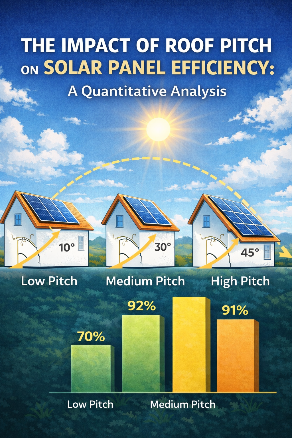
Lorsque l'angle réel du toit () diffère de l’inclinaison théoriquement optimale (), l'écart qui en résulte réduit directement le rayonnement incident et, par conséquent, production annuelle d'énergie. Les données industrielles et les études de simulation fournissent des estimations quantifiables de ces pertes.
Selon le Laboratoire National des Energies Renouvelables (NREL), les écarts de10 degrees de l'inclinaison optimale peut réduire la production annuelle d'énergie d'environ5% , tandis que les écarts de20 degrees peut entraîner des pertes allant de10% à 15% [9]. Ces résultats concordent avec les observations pratiques des bases de données d'installations photovoltaïques.
Une étude de simulation détaillée réalisée pour un emplacement à 31° de latitude nord (comparable à Shanghai) examiné la relation entre l'inclinaison du panneau et la perte d'efficacité par rapport à l'angle optimal de 31° [10]:
| Angle d'inclinaison du panneau | Perte d'efficacité annuelle par rapport à. Optimal (31°) |
|---|---|
| 5° | 3.6% |
| 15° | 0.8% |
| 25° | 0% |
| 30° | 0.5% |
| 40° | 2.7% |
Données adaptées de simulations de performances photovoltaïques à 31° de latitude N [10]
L'implication pratique de ces résultats est remarquable: pour les écarts dans un10-20 plage de degrés de l'optimum, la perte annuelle de puissance de sortie est généralement modeste, entre1% et 5% [11]. Cela explique pourquoi les installateurs solaires acceptent généralement des angles d'inclinaison compris entre 15° et 35° pour les emplacements proches de 30° de latitude., car les pertes marginales sont économiquement justifiables par rapport au coût des structures de montage personnalisées [12].
Les pénalités les plus importantes surviennent lorsque les panneaux sont installés presque à plat ou à des inclinaisons extrêmes loin de l'optimum.. Par exemple, panneaux à encastrer sur un toit résidentiel à faible pente (22.5° pas) où l'angle optimal est de 40° peut entraîner des pertes annuelles de5-8% par rapport à un système de montage au sol incliné de manière optimale [13].
🔍 Facteurs critiques affectant les performances du système solaire
Bien que l'angle d'inclinaison soit un paramètre de conception important, il ne représente qu'un composant d'un problème d'optimisation complexe. La recherche indique que d'autres variables peuvent exercer une influence égale ou supérieure sur le rendement énergétique final. [14].
Orientation (Angle d'azimut)
Dans l'hémisphère nord, l'orientation optimale est le sud vrai. Deviations from this azimuth introduce compounding losses when combined with suboptimal tilt. Simulations demonstrate that an array facing 30° off true south can experience total losses exceeding20% when tilt is also non-optimal. At 60° azimuth deviation, generation losses may reach20-30% annually [15].
Shading Effects
Partial shading represents one of the most significant threats to system performance. Even minimal shading on a single panel can trigger disproportionate losses across an entire string due to the electrical configuration of series-connected modules. Studies document shading-related efficiency reductions of10% ou plus in urban residential installations [16].
Installation Quality and Maintenance
Field studies reveal that practical installation factors substantially impact realized performance. Poor electrical connections, suboptimal inverter sizing, et une inadéquation de tension peut réduire collectivement la sortie du système. En outre, la saleté due à l'accumulation de poussière et de débris a été mesurée pour réduire la production jusqu'à5% en milieu urbain, avec des pertes plus élevées dans les régions arides ou agricoles [17].
📊 Conclusion: Implications pratiques pour la conception du système
La relation entre la pente du toit et l'efficacité des panneaux solaires est régie par des principes géométriques bien établis exprimés par des équations de rayonnement solaire.. Tout en faisant correspondre l'angle du toit à l'inclinaison optimale, on maximise théoriquement la production, les données disponibles démontrent que des écarts modérés entraînent des pertes annuelles étonnamment modestes, généralement 1-5% pour des angles compris entre 15 et 20° par rapport à l'optimum.
Ces résultats ont des implications pratiques pour les installations solaires résidentielles et commerciales: the incremental benefit of achieving perfect tilt is often outweighed by the cost of custom racking systems, particularly when compared to flush-mounted installations on existing roof structures. A holistic approach to system design that optimizes orientation, minimizes shading, and ensures quality installation will yield greater long-term performance gains than pursuing perfect tilt angle at the expense of other factors [18].
This article was generated by AI under the supervision of an Adult 😉
📚 Références
[1] Duffie, J. A., & Beckman, DE. Une. (2013). Solar Engineering of Thermal Processes (4th ed.). John Wiley & Sons, pp. 12-15.
[2] Masters, Sol. M. (2004). Renewable and Efficient Electric Power Systems. John Wiley & Sons, pp. 385-390.
[3] Laboratoire national des énergies renouvelables. (2021). “Solar Radiation Basics.” NREL Technical Report, Golden, CO.
[4] Jacobson, M. Z., & Jadhav, En. (2018). “World estimates of PV optimal tilt angles and ratios of sunlight incident upon tilted and tracked PV panels relative to horizontal panels.” Énergie solaire, 169, pp. 55-66.
[5] Liu, B. Et. H., & Jordanie, R. C. (1963). “The long-term average performance of flat-plate solar-energy collectors.” Énergie solaire, 7(2), pp. 53-74.
[6] Honsberg, C., & Bowden, S. (2019). “Photovoltaics Education Website.” PVEducation.org, Section: “Solar Radiation on Tilted Surfaces.”
[7] Messager, R. A., & Ventre, J. (2010). Photovoltaic Systems Engineering (33e éd.). CRC Press, pp. 45-49.
[8] Lave, M., & Kleissl, J. (2011). “Optimum fixed orientations and benefits of tracking for capturing solar radiation in the continental United States.” Energies Renouvelables, 36(3), pp. 1145-1152.
[9] Laboratoire national des énergies renouvelables. (2020). “PVWatts Calculator: Methodology Documentation.” NREL/TP-6A20-6858, Golden, CO.
[10] Soleil, Y., et al. (2018). “Optimum tilt angle for photovoltaic systems in different climate zones.” Energy Procedia, 152, pp. 116-121.
[11] Rowlands, Je. H., Kemery, B. P., & Beausoleil-Morrison, Je. (2011). “Optimal solar-PV tilt angle and azimuth: An Ontario (Canada) case-study.” Politique énergétique, 39(3), pp. 1397-1409.
[12] Clean Energy Council. (2020). “Grid-Connected Solar PV Systems Installation Guidelines.” Australian Government, pp. 23-25.
[13] Kaldellis, J. K., & Zafirakis, D. (2012). “Experimental investigation of the optimum photovoltaic panels’ tilt angle during the summer period.” Énergie, 38(1), pp. 305-314.
[14] Agence internationale de l'énergie. (2019). “Design and Operation of PV Systems.” IEA-PVPS Task 13 Report, T13-12:2019.
[15] Hartner, M., et al. (2015). “Est-ouest – L’angle d’inclinaison et l’orientation optimaux des panneaux photovoltaïques du point de vue du système électrique.” Énergie appliquée, 160, pp. 94-107.
[16] Déline, C., et al. (2013). “Une analyse des performances et de l'économie de l'électronique de puissance distribuée dans les systèmes photovoltaïques.” NREL Technical Report, TP-5200-50003.
[17] Maghami, M. R., et al. (2016). “Perte de puissance due à l'encrassement du panneau solaire: Une revue.” Examens des énergies renouvelables et durables, 59, pp. 1307-1316.
[18] Luc, A., & Hégédus, S. (2011). Manuel de science et d'ingénierie photovoltaïques (2nd ed.). John Wiley & Sons, pp. 905-940.