
Harmonic Control at a Remote Oil Well: Better Than 18-Pulse Performance at 12-Pulse Cost — Mirus International
| Location | Simonette well site, far Northern Alberta |
| Client | Chevron Canada |
| Application | Submersible pump drive — remote, unmanned oil well |
| Service transformer | 200 kVA |
| Drive | 150 kVA, 480 V adjustable speed drive |
| Motor | 150 HP |
| Load configuration | Drive is the only load on the transformer |
| Harmonic filter | Mirus Lineator AUHF 150 HP |
| Performance | Better than 18-pulse; 9% less expensive than 12-pulse drive option |
01 Operating Context: Unmanned Remote Well Sites in Northern Alberta
Chevron operates adjustable speed drives on submersible pump motors at remote, unmanned oil wells across far Northern Alberta. These sites share a common electrical architecture: a single service transformer feeds a single VSD, which controls a single submersible pump motor. There is no other load on the transformer. The sites are completely unmanned — visited periodically for maintenance, monitored remotely the rest of the time.[1]
This configuration creates two distinct requirements that pull in opposite directions. The single-drive-on-transformer topology is the worst-case harmonic scenario — the drive is the only load, so there is no linear load current to dilute the harmonic content, and the current drawn from the transformer is essentially the raw harmonic spectrum of a 6-pulse rectifier. At the same time, the unmanned and remote nature of the site demands maximum reliability — a harmonic problem that causes a drive trip or a communication system failure means a well that stops producing, with no one on site to respond.
Chevron’s engineering team took a proactive, preventive approach: rather than waiting for harmonic problems to manifest at well sites, they established a standard specification for harmonic mitigation on all low-voltage, single-drive well sites up to 1,000 HP. The Simonette well site represents the application of that standard.[1]
Fig. 1. Chevron’s Simonette well site, far Northern Alberta. The 200 kVA service transformer and 150 HP VSD enclosure are visible. Single drive, unmanned, remote. Source: Mirus International / Chevron.[1]
02 The Single-Drive Problem: Harmonics With No Dilution
2.1 Why this topology is particularly sensitive
A 6-pulse VSD draws current in characteristic pulses — the familiar double-humped waveform per half-cycle that contains predominantly 5th, 7th, 11th, and 13th harmonic components. On a large industrial bus with many loads, these harmonics mix with the fundamental-frequency currents from motors, lighting, and other linear loads, and the resulting THDi at the bus is lower than what any single drive would produce alone.
At the Simonette well site, none of this dilution exists. The transformer secondary feeds only the VSD. The transformer primary sees only the distorted VSD current. The voltage distortion on the transformer secondary — which is also the supply voltage to the drive control electronics and any communication equipment at the site — reflects the full harmonic content of the 6-pulse rectifier through the transformer impedance.[1]
2.2 Communication system vulnerability
Remote well sites rely on SCADA and telemetry systems for monitoring and control. These systems share the site electrical supply. Voltage distortion and high-frequency harmonic content can interfere with the sampling and communication circuits of SCADA equipment, causing false readings, communication dropouts, or equipment lockups. In an unmanned application, a communication failure means lost visibility into well production — a direct financial consequence with no personnel on site to diagnose or reset the system.[1]
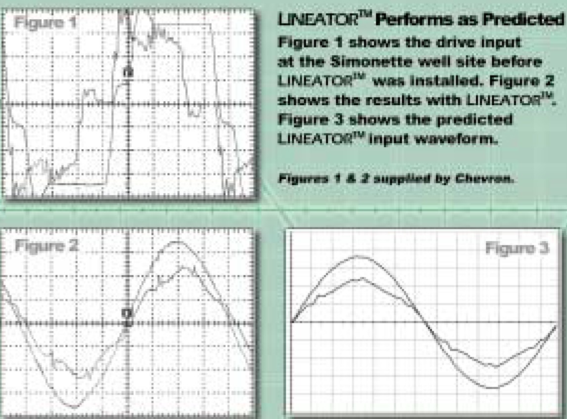
Fig. 2. Current waveforms at the Simonette well site. Left: drive input before Lineator installation — characteristic 6-pulse distortion. Centre: measured result with Lineator installed — near-sinusoidal. Right: predicted Lineator input waveform from simulation. Figures 1 and 2 supplied by Chevron.[1]
03 Multi-Pulse Drives vs. the Lineator: A Technology Comparison
Chevron’s electrical engineers were experienced users of multi-pulse drive technology. Before selecting the Lineator, they specifically evaluated 12-pulse and 18-pulse drive options against the Lineator AUHF for this application. The comparison is instructive.[1]
3.1 How multi-pulse drives work
A 12-pulse drive uses a phase-shifting transformer with two secondary windings — one wye and one delta — to feed two 6-pulse rectifier bridges in parallel. The 30° phase shift between the windings causes the 5th and 7th harmonic currents from the two bridges to cancel in the transformer primary, leaving the 11th and 13th as the dominant harmonics. An 18-pulse drive extends this to three phase-shifted secondary windings feeding three bridges, cancelling through the 13th harmonic and leaving the 17th and 19th.[2]
Both approaches reduce THDi substantially compared to a standard 6-pulse drive. But they carry specific costs and constraints that made them problematic for the Simonette application.
3.2 The comparison
| Criterion | 12-pulse drive | 18-pulse drive | Lineator AUHF |
|---|---|---|---|
| Harmonic performance | Good — cancels 5th & 7th | Better — cancels through 13th | Better than 18-pulse (measured) |
| Capital cost vs. 12-pulse | Baseline | Higher | 9% less than 12-pulse |
| Factory testing required | Yes — phase shift & load sharing | Yes — more complex | No |
| Installation complexity | Moderate | Higher | Plug and play |
| Drive supplier endorsement | Standard offering | Available | Fully tested & recommended |
| Performance sensitivity to load | Degrades at light load | Degrades at light load | Robust across load range |
The drive supplier endorsement carries weight in this context. Chevron was not evaluating an unknown product — the Lineator had been tested by the drive manufacturer for compatibility with their specific drive platform. This eliminated the integration risk that can accompany third-party harmonic filters and was a decisive factor in the selection.[1]
04 Results: Performance as Predicted, Cost Below Alternatives
The Lineator AUHF was installed at the Simonette well site on the 150 HP, 480 V drive. Measured current waveforms confirmed the simulation predictions: the drive input current waveform was transformed from the characteristic distorted 6-pulse pattern to a near-sinusoidal shape.[1]
The measured harmonic performance exceeded 18-pulse drive specifications — the most demanding multi-pulse standard Chevron had previously used. This was achieved at a capital cost 9% below a 12-pulse drive configuration, with simpler installation (no factory pre-testing required) and full compatibility confirmation from the drive supplier.
Cost effectiveness: Better harmonic performance than 18-pulse at lower cost than 12-pulse. No factory testing costs. Plug-and-play installation. Standard solution deployable across all single-drive well sites up to 1,000 HP.
05 The Power Quality Perspective: What This Case Study Illustrates
5.1 The single-drive-on-transformer scenario — a common field condition
Remote well sites, irrigation pump stations, small water treatment facilities, and similar single-load installations share the same electrical topology as Simonette: one transformer, one VSD, no other loads. This topology appears throughout rural infrastructure wherever a pump or compressor is the sole electrical load at a remote site.
From a utility standpoint, these single-drive installations are PQ problems waiting to develop. The transformer sees high THDi continuously, runs hot, and ages faster. If the transformer feeds any utility-side measurement equipment, communication relays, or revenue metering, harmonic distortion affects their accuracy and reliability. Chevron’s proactive approach — standard harmonic mitigation on all single-drive well sites — is the correct engineering response and produces lower lifecycle costs than reactive mitigation after failures occur.
5.2 Multi-pulse drives — when they make sense and when they don’t
Multi-pulse drives (12-pulse and 18-pulse) are effective harmonic mitigation when the application justifies their cost and complexity. They make most sense for large, high-utilization drives where the phase-shifting transformer is a minor fraction of total system cost, where load is relatively constant (avoiding the light-load performance degradation), and where the harmonic cancellation can be verified by factory testing before shipment.
They are less well-suited to small drives (the transformer cost becomes a significant fraction of drive cost), variable-load applications, and situations where field installation simplicity is valued. The Simonette well site failed all three of the conditions that favour multi-pulse — small drive, variable pump load, remote unmanned installation requiring simple maintenance. The technology comparison led directly to the correct conclusion.
5.3 Preventive vs. reactive harmonic management
Chevron’s decision to specify harmonic mitigation as a standard requirement across all single-drive well sites — before problems occurred — is worth noting as a management approach, not just an engineering one. The cost of a harmonic filter at installation is far lower than the cost of diagnosing and resolving harmonic problems after the fact: transformer replacement, drive repairs, SCADA system troubleshooting, and lost production during unplanned downtime. Preventive harmonic management is straightforward to justify when the single-point, high-impedance topology makes the harmonic outcome predictable from day one.
This case study concludes the IPQDF series of Mirus International case studies. Taken together — ESP motor protection, pipeline generator rightsizing, offshore vessel DP compliance, natural gas processing plant MCC mitigation, and remote well site harmonic control — they cover the major categories of generator-fed and supply-constrained harmonic applications encountered in the oil and gas, marine, and process industries. The common thread is a high source impedance that amplifies harmonic consequences beyond what utility-connected engineers typically encounter, and a passive wide-spectrum filter that addresses the problem without adding the complexity and failure modes of active or multi-pulse solutions.
References
- [1] Mirus International Inc., “Case Study: Chevron’s Simonette Well Site,” Application Case Study, Mississauga, Ontario, Canada. Available: mirusinternational.com
- [2] IEEE Std 519-2022, “IEEE Standard for Harmonic Control in Electric Power Systems,” IEEE, New York, NY, 2022.