
Sinewave Filters for ESP Motor Protection: A Field Case Study in Filter Design and Motor Thermal Response — Mirus International
01 Operating Context: ESPs and the Artificial Lift Problem
Over 90% of onshore and offshore oil wells worldwide require some form of artificial lift to sustain production. The most widely deployed technology is the Electrical Submersible Pump (ESP) — a multistage centrifugal pump driven by a downhole induction motor, controlled from surface by an adjustable speed drive (ASD).[1]
This combination creates two distinct power quality problems that sit on opposite ends of the ASD:
- Input side: The 6-pulse front-end rectifier of the ASD injects characteristic current harmonics (5th, 7th, 11th, 13th…) back into the supply network — a well-understood problem with well-understood mitigation options.
- Output side: The PWM inverter stage generates a high-frequency switched voltage waveform that — when applied to a long motor cable — produces voltage overshoots, reflected wave transients, and harmonic-induced heating in the downhole motor.
In an oil field in Montana, all PWM-operated ESPs were equipped with output sinewave filters to address the second problem. Despite this precaution, the sinewave filters themselves began failing — often within six months of installation. When filters failed, operators were forced to switch drives to 6-Step mode (no PWM, no sinewave filter needed), which eliminated the reflected-wave problem but introduced a different set of stresses. Motors in 6-Step mode run hotter, and motor failures continued.[1]
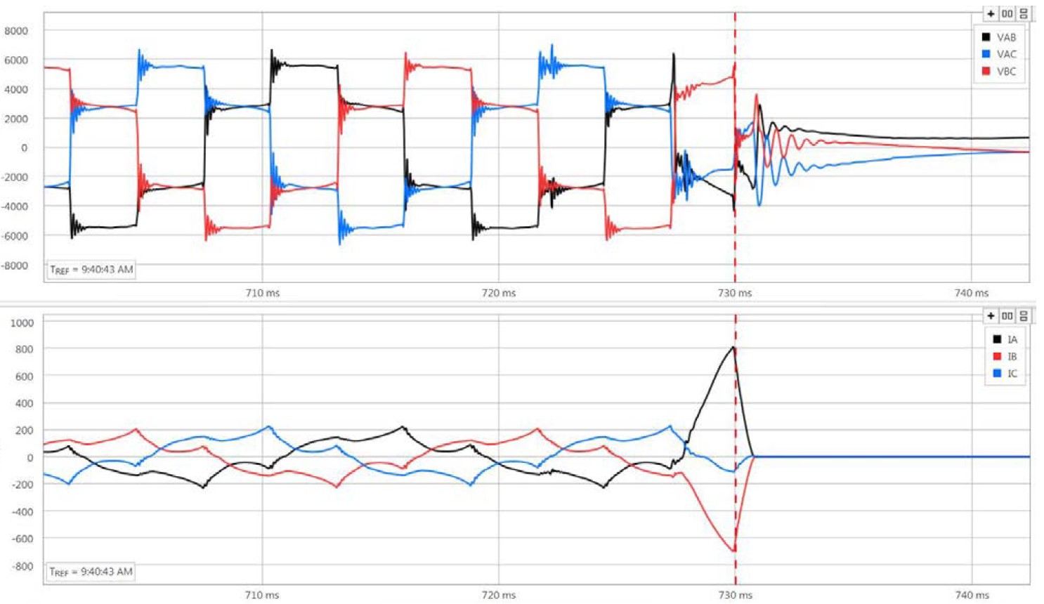
Fig. 1. Voltage (top) and current (bottom) on a 6-Step ESP at the moment of motor failure. Note the sustained overvoltage ringing in the pre-fault period. Source: Mirus International case study.[1]
02 Problem Anatomy: Why PWM Is Hard on Submersible Motors
2.1 The reflected wave mechanism
A PWM inverter switches its DC bus voltage across the output terminals at the carrier frequency — typically 2 to 8 kHz for ESP drives, with larger drives using the lower end of that range. Each switching transition is a very fast voltage step (high dv/dt). When this step propagates along the cable connecting the drive to the motor, it encounters an impedance discontinuity at the motor terminals. The resulting voltage reflection can produce peak voltages approaching twice the DC bus voltage.[2]
For a standard 480 V drive, the DC bus sits near 675 V. A reflected wave overshoot can therefore momentarily impose 1,200–1,350 V on the motor winding insulation — well above the design withstand capability of motors not rated for inverter duty.
2.2 Capacitive stress at the first winding turn
At the switching frequencies used in PWM drives, the distributed inductance and turn-to-turn capacitance of a motor winding form a lossy transmission line. The voltage wavefront does not distribute evenly across turns — the first few turns of the winding must absorb a disproportionate share of the surge. This is the first-turn problem, and it is the primary failure mechanism for motor winding insulation in PWM-driven applications.[2]
2.3 Why 6-Step mode does not solve the problem
6-Step operation drives the motor with a quasi-square wave at fundamental frequency, eliminating the high-frequency PWM switching and its associated transients. However, the quasi-square wave is rich in low-order harmonics — primarily the 5th and 7th. These harmonics generate counter-rotating magnetic fields in the stator, producing additional copper and iron losses that increase motor temperature. In the ESP application, higher operating temperature accelerates seal degradation and insulation aging.[1]
The conclusion is clear: the right solution is not to remove PWM, but to filter it effectively.
03 Filter Design: Tuning Frequency as the Critical Parameter
3.1 What a sinewave filter must do
A sinewave filter is a low-pass LC filter inserted between the inverter output and the motor terminals. Its function is to attenuate the switching-frequency harmonics sufficiently that the voltage seen by the motor approximates a sinusoid at the fundamental drive output frequency. Two performance criteria were set for the redesign effort:[1]
- Voltage total harmonic distortion at filter output: < 3% THDv
- Current total harmonic distortion at inverter output: < 5% THDi
An additional design constraint — critical for long-term reliability — was that the filter must limit system resonance inherently, without relying on damping resistors that add insertion loss and generate heat.
3.2 The resonance problem with conventional tuning
Conventional sinewave filters for 60 Hz systems are typically tuned near 600 Hz (the 10th harmonic). Computer analysis of a 200 HP, 480 V, 60 Hz ESP system with a 600 Hz tuned filter and a 2 kHz inverter switching frequency produced 9.1% THDv — worse than the target and indicative of a resonance condition. Adding resistive damping reduced the resonance but not to a level that produced acceptable distortion. The conventional design was fundamentally unsuitable for this application.[1]
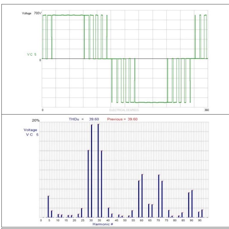
Fig. 2. Inverter output PWM voltage waveform and harmonic spectrum at 2 kHz switching frequency. THDv ≈ 39.6%. Source: Mirus International.[1]
3.3 The 180 Hz solution
When the tuned frequency was lowered to 180 Hz (the 3rd harmonic of 60 Hz), resonance disappeared even without damping resistors. The filter output THDv dropped below 2% for both the 200 HP and the 1,100 HP ESP systems. The 180 Hz cutoff places the filter’s natural frequency well below the carrier harmonics, ensuring robust attenuation across the entire switching-frequency range regardless of carrier frequency variations.[1]
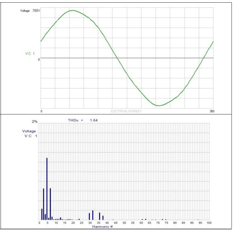
Fig. 3. Output voltage waveform and spectrum with 180 Hz tuned sinewave filter. THDv drops to approximately 1.64% — well within the < 3% design target. Source: Mirus International.[1]
3.4 Secondary performance improvements
| Parameter | Conventional filter (600 Hz tuning) | INVERSINE filter (180 Hz tuning) |
|---|---|---|
| Output THDv | ~9.1% (with resonance) | < 2% |
| Insertion voltage drop (full load) | ~10% | < 3% |
| Power factor at inverter output | Lagging (motor reactive load) | Near unity (capacitors compensate motor VAr) |
| Damping resistors required | Yes (still insufficient) | No — inherent damping from LC tuning |
The lower insertion loss (10% vs. 3%) means the motor receives proportionally higher terminal voltage at a given inverter output setting, which reduces motor current and the associated I²R losses — directly contributing to lower operating temperature.
The near-unity power factor at the inverter output reduces ASD output current for the same shaft power, reducing inverter losses and extending drive service life. In ESP applications where the motor is sized close to the ASD rating, this current reduction can allow a modest increase in pump speed — and therefore production rate.
04 Field Results: Motor Temperature as the Diagnostic Variable
An 1,100 HP, 480 V, 60 Hz INVERSINE filter (180 Hz tuning) was installed on a well that had been operating in 6-Step mode following sinewave filter failure. After installation, the drive was switched back to PWM operation. Downhole motor temperature was monitored continuously via the ESP instrumentation package.[1]
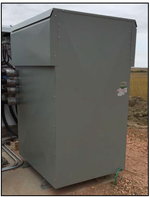
Fig. 4. The 1,100 HP INVERSINE AUSF sinewave filter installed at the wellsite. Source: Mirus International.[1]
4.1 Steady-state temperature reduction
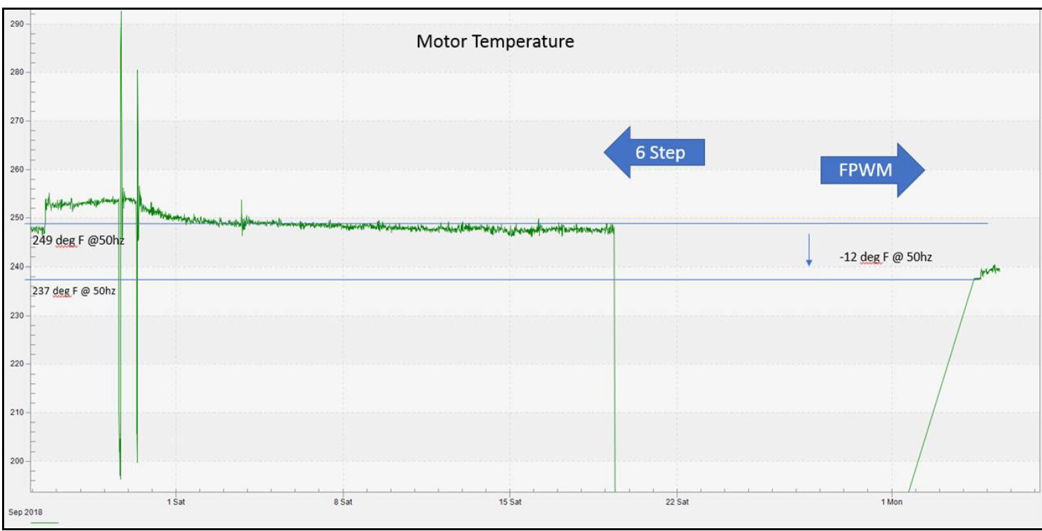
Fig. 6. Motor operating temperature trend showing the transition from 6-Step to FPWM operation with the INVERSINE sinewave filter. A 12 °F steady-state reduction is immediately apparent. Source: Mirus International.[1]
Steady-state motor temperature dropped from 249 °F to 237 °F — a 12 °F (approximately 5%) reduction — immediately after switching to PWM with the new filter. This improvement is attributable to two factors acting together: elimination of the 5th and 7th harmonic heating that is characteristic of 6-Step operation, and the reduced copper losses resulting from lower motor current at improved terminal voltage.
4.2 Startup temperature spike reduction
Startup transients are particularly damaging for ESP motors because of a specific failure mode linked to the motor seal section. During startup, motor temperature rises sharply as current is well above rated. The elevated temperature causes motor oil in the mechanical seal to expand and discharge into the wellbore. As the motor cools after shutdown, the contracting oil draws wellbore fluid (with its solids and corrosives) back into the seal. Repeated thermal cycling progressively contaminates the seal, accelerating wear.[1]
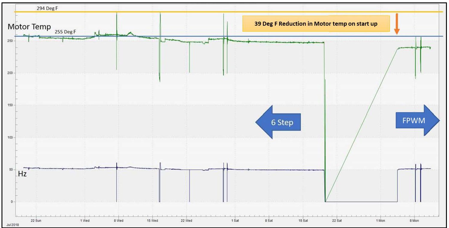
Fig. 7. Motor temperature during start-stop cycles, comparing 6-Step and PWM with INVERSINE filter. The 39 °F reduction in startup temperature spikes directly reduces the thermal stress on the self-equalizing seal section. Source: Mirus International.[1]
4.3 Production rate improvement
The specific wellsite in the case study did not have a pump/motor combination large enough to exploit the current reduction from the improved power factor. However, when a similar filter was installed at a second wellsite, an increase of 125 barrels per day (BPD) of total fluid production was reported — the direct result of being able to push the pump to a slightly higher speed with the headroom freed by reduced ASD current.[1]
4.4 Waveform quality comparison
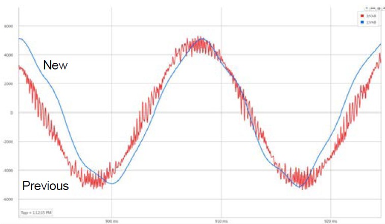
Fig. 5. Voltage waveform comparison at motor terminals: new 180 Hz tuned filter (top, clean sine) vs. conventional filter (bottom, residual PWM ripple visible). Source: Mirus International.[1]
05 The Power Quality Perspective: What This Case Study Illustrates
A utility power quality background gives a different perspective on what happened in the Montana oil field. The sequence of failures was not simply a product quality problem with the original sinewave filters — it was a system resonance problem that the conventional filter design approach failed to anticipate.
5.1 The compliance paradox in ESP filter design
Conventional sinewave filter designs for 60 Hz industrial applications tune near 600 Hz. This choice works acceptably on standard motor loads with short cables. In the ESP application, the long downhole cable dramatically changes the impedance seen at the inverter output terminals. The motor-cable system has its own resonant frequencies, and these can fall near the filter’s tuning frequency — turning the filter from an attenuator into an amplifier at those frequencies. A 9.1% THDv result with a “standard” filter is not a defective filter; it is a correctly manufactured filter operating in a system for which it was not designed.[1]
5.2 Thermal measurements as a PQ diagnostic tool
The case study uses continuous downhole motor temperature as its primary validation metric — not harmonic spectrum measurements, not power analyzer data. This is pragmatically correct for the ESP application: downhole PQ measurements are difficult and expensive to obtain, but temperature sensors are integral to the ESP instrumentation package and provide a real-time, integrated measure of motor stress. The 39 °F reduction in startup temperature spikes is a more meaningful indicator of improved motor health than any THD number measured at the surface.
From a PQ measurement methodology standpoint, this illustrates an important principle: choose the metric closest to the consequence you are trying to prevent. In this case, that metric is motor temperature, not voltage distortion.
5.3 The two-sided nature of VFD power quality
Articles 1 and 2 in this series addressed harmonic problems on the supply side of a VFD — the current harmonics injected by the 6-pulse rectifier, and the interaction of those harmonics with power factor correction capacitors. This case study sits on the opposite side of the same device: the output voltage quality problems created by the PWM inverter.
Both sides of the VFD matter. Supply-side harmonics affect network power quality and other equipment sharing the same bus. Output-side harmonics affect the driven motor directly. A complete treatment of VFD power quality requires considering both. Article 4 in this series will continue this theme, examining the 6-pulse rectifier as a victim rather than a source — specifically, how poor supply voltage quality degrades rectifier performance and affects the DC bus seen by the inverter.
References
- [1] Mirus International Inc., “INVERSINE Sinewave Filter Resolves ESP Motor Failures,” Application Case Study, Brampton, Ontario, Canada. Available: mirusinternational.com
- [2] A. von Jouanne, D. Rendusara, P. Enjeti, and J. Gray, “Filtering Techniques to Minimize the Effect of Long Motor Leads on PWM Inverter-Fed AC Motor Drive Systems,” IEEE Transactions on Industry Applications, vol. 32, no. 4, pp. 919–926, Jul./Aug. 1996.